

Capable of supporting up to 32 GT/s without altering design
Understanding Slew Rate in Op-Amp and How to Measure and Calculate it for your Designs

An ideal op-amp is a voltage amplifier with infinite input impedance, zero output impedance, and infinite bandwidth. In the real world, however, these parameters are limited by small imperfections in semiconductor manufacturing, effects of temperature, and so on. There is one parameter that is much overlooked but stands out in the above regard, and that is the slew rate. It is not a parasitic effect, but rather a deliberate slowing down of the op-amp to ensure stability.
In this article, we will learn about the slew rate of an operational amplifier, and where it comes from, and we will also do some calculations for the classic 741 op-amp.
What is Slew Rate?
The slew Rate is defined as the maximum rate of change of an opamp’s output voltage. In other words, Slew rate basically refers to how fast the op-amp is capable of changing its output voltage in response to a change in input. The slew rate is usually measured in units of a volt per unit of time, more commonly in volts per microsecond, or V/µs.
Unit of Slew Rate = V/uS
An ideal op-amp has an infinite slew rate, meaning it can change its output instantly with any change in input. It is usually measured by giving a step signal to the input of the opamp and measuring the rate of change from 10% to 90% of the output signal’s amplitude.
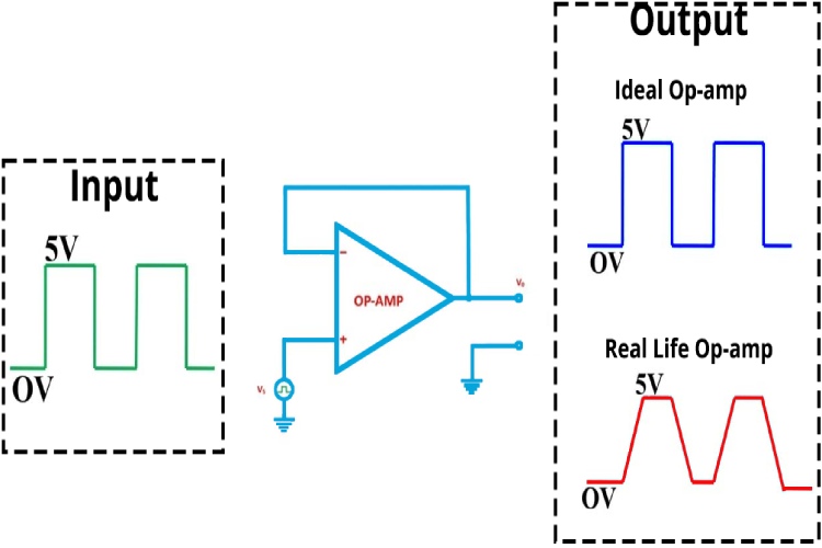
To understand it more easily let's look at an example. In the above image, you can see that we have configured an op-amp as a voltage follower. Ideally, the output should follow the input signal. On the input side of the voltage follower, we are applying a square wave signal, which is marked in green colour. Ideally, the output should have the same waveform without any distortions, which is displayed as the blue-coloured waveform. But in reality, that's not the case. Output won’t be the same as the input because of the slew rate and many other factors. The waveform in the red colour is a representation of the output, due to the slew rate.
The diagram given below shows the output of an op-amp in response to a step input.
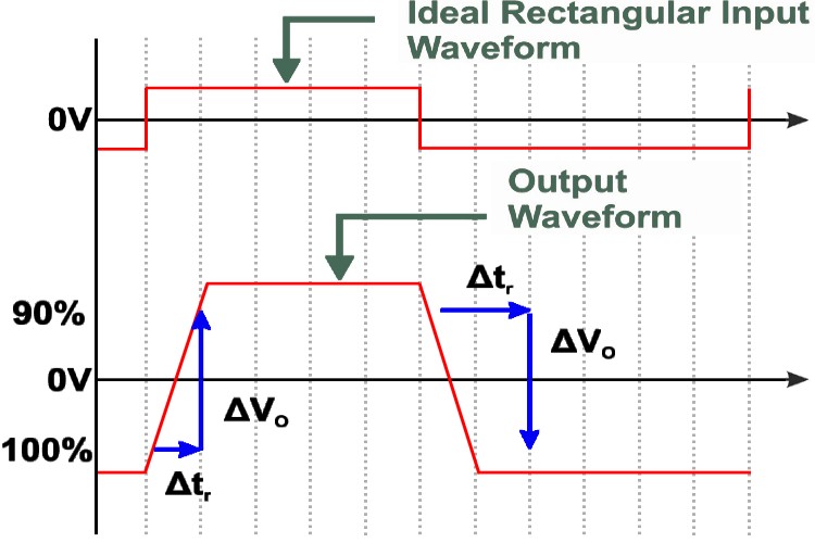
As we can see in the diagram, the output voltage does not rise immediately following the input. The op-amp has a finite rise time, where the voltage increases linearly with time. This slope of the output voltage with respect to time is the slew rate.
Why Are Op-Amps Slew Rate Limited?
As we have discussed the frequency compensation plays a big role in the slew rate of an op-amp. But that is not the only thing that affects the slew rate. This limitation arises due to several intrinsic factors of the op-amp's design and operation:
- Internal Compensation Capacitance: Most op-amps are internally compensated to ensure stability across a wide range of feedback configurations. This compensation involves adding a small capacitor inside the op-amp, which limits the speed at which the internal nodes of the amplifier can change voltage. This capacitor, in conjunction with internal resistances, forms an RC time constant that inherently limits the rate at which the output can change, directly affecting the slew rate.
- Current Limiting: The internal circuitry of an op-amp can only source or sink a finite amount of current due to its design and the limitations of the transistors used. This finite current capability means that charging or discharging the internal compensation capacitor (and any load capacitance) can only happen so fast, thereby limiting the slew rate. The available current, in conjunction with the load the op-amp is driving, will determine how quickly the output can change.
- Supply Voltage: The slew rate can also be influenced by the supply voltage. Higher supply voltages generally allow for a wider output voltage swing and potentially faster charging and discharging of internal capacitive loads, which can improve the slew rate. However, the internal design and current limiting still play a more significant role in defining the maximum achievable slew rate.
- Capacitive Loading: Inside an op-amp, there are internal capacitances, particularly at the compensation node, which are used to ensure the stability of the amplifier. When the input signal changes rapidly, these capacitances need to charge or discharge, but the finite current available from the internal circuitry limits how quickly this can happen, thus limiting the slew rate.
- Temperature and Process Variations: The performance characteristics of the semiconductor materials and components used in op-amps can vary with temperature and manufacturing process variations. These variations can affect the current carrying capabilities of the transistors and the characteristics of the internal capacitors, thus impacting the slew rate.
- Design Trade-offs: Op-amp designers face trade-offs between slew rate, bandwidth, noise performance, and power consumption. Improving one aspect often requires compromising another. For instance, increasing the bias current in the amplifier can improve the slew rate but at the cost of higher power consumption and potentially more noise.
The slew rate limitation is significant because it determines how quickly an op-amp can respond to changes in the input signal, affecting its ability to accurately reproduce fast-changing signals, especially at high frequencies. If the input signal changes more quickly than the op-amp's slew rate, the output will not accurately follow the input, leading to distortion, particularly in applications involving high-frequency signals or large voltage swings. Understanding and designing with the slew rate in mind is crucial for ensuring that the op-amp can meet the performance requirements of the application.
Impact of Input Signal Characteristics on Slew Rate
While the inherent slew rate of an op-amp is determined by its internal design, the characteristics of the input signal can also influence how the slew rate affects circuit performance. Understanding these influences is essential for designing effective circuits that operate within the desired specifications. Here, we explore various input signal parameters and how they can impact the effective slew rate in a circuit.
- Amplitude of the Input Signal: The amplitude of the input signal plays a significant role in determining the demand on the op-amp's slew rate. A larger voltage swing requires the output to change more rapidly, which means the op-amp must have a sufficiently high slew rate to accommodate this change without distorting the signal. If the input signal demands a rate of change faster than the op-amp can provide, the output will exhibit a slower transition than the input, leading to waveform distortion, particularly in high-frequency or large-signal applications.
- Frequency of the Input Signal: The frequency of the input signal is directly related to how quickly the output needs to respond. High-frequency signals require the output voltage to change rapidly, increasing the demand on the slew rate. For sine waves, the slew rate requirement is calculated as SR 2fVPeak, Where f is the frequency and VPeakis the peak voltage of the signal. If the op-amp’s slew rate is lower than what the frequency and amplitude of the input signal require, it will result in a distorted output where the signal is unable to follow the input waveform accurately, particularly at the peaks of the waveforms.
- Rise and Fall Times of the Input Signal: The rise and fall times of an input signal, which are particularly relevant for digital signals like square waves, determine how quickly the signal transitions from one level to another. Op-amps with insufficient slew rates will struggle to replicate sharp transitions, leading to rounded edges in the output signal. This effect can degrade the performance of digital circuits, where precise timing is critical, and can also introduce timing errors, signal integrity issues, or even data loss in high-speed communication applications.
Frequency Compensation and Slew Rate
The output swing is deliberately limited in op-amps to ensure stability through the use of a compensation capacitor, which provides frequency compensation and limits the output slew rate. The figure given below shows the effects of having frequency compensation in an op-amp.
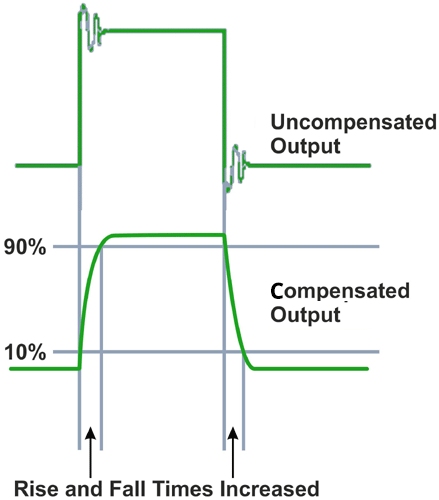
Although uncompensated op-amps are faster, because of the fast-rising and falling edges, there is ringing present, and this can lead to stability issues. To avoid this, compensation is implemented by adding a Miller capacitor to the driver stage of the op-amp.
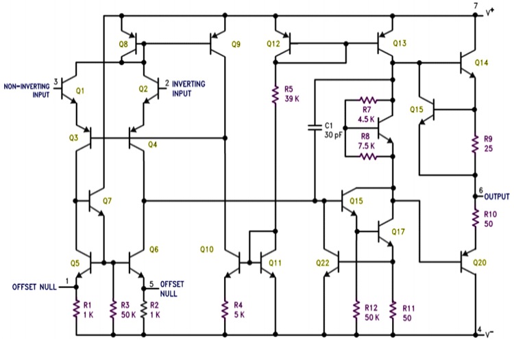
In the above figure, which shows the internal schematics of a typical op-amp, the compensation capacitor is C1, with a small value of 30pF. It is placed between the input and output of the output transistor driver. This can be simplified in the below figure.
Here, a capacitor is added between the base and the collector. This capacitor is sometimes referred to as a Miller capacitor because it is similar to the parasitic Miller capacitance between the base and collector of a BJT transistor. As the input rises, the output on the collector begins to fall. This creates a voltage difference across the capacitor, and a current begins to flow through it.
Following the simple formula that relates voltage, current, capacitance, and time for a capacitor:
ic= C x dv/dt
where ic is the capacitor current, C is Capacitance and dv/dt is rate of change of voltage.
From this, we can get that
slew rate dv/dt = ic/C.
We can understand that the voltage across the capacitor increases in a linear fashion. This voltage is seen across the output and looks like a ramp waveform. This prevents the output from changing abruptly when the input changes and the output slew rate is determined by the capacitance of the compensation capacitor and the driving current. This basic principle is used to compensate for almost all op-amps.
How to Calculate the Slew-rate of an Op-Amp?
There are two ways one can follow for measurement of Slew Rate. The first is to measure the output swing using an oscilloscope and using the following Slew Rate Formula to calculate the slew rate:
Slew Rate = (Vi - Vf)/(ti - tf)
Where Vi is the initial voltage, Vf is the final voltage, ti is the time when the initial voltage is measured, and tf is the time when the final voltage is measured. The unit of slew rate is always given in volts per microsecond. This method is easily done using an oscilloscope and cursors. Now, if we apply the same formulae for an ideal op-amp, the time delay (ti – tf) will be zero and hence the slew rate will be infinity. So, in theory, the slew rate of the ideal op-amp will always be infinity.
Often, the initial voltage is taken to be 10% of the maximum value and the final voltage is 90% of the maximum value since this is the common range which is measured as rise time. The slew rate value is always given in the datasheet of the respective op-amp. In a datasheet, the large-step signal response indicated the slew rate of the op-amp.
Slew Rate Calculation for 741 Opamp
The LM741 is a classic op-amp that has been around for a very long time and is the perfect specimen for this example. In every op-amp datasheet, one can find a plot of the large-signal output response. We will use this plot to calculate the slew rate.
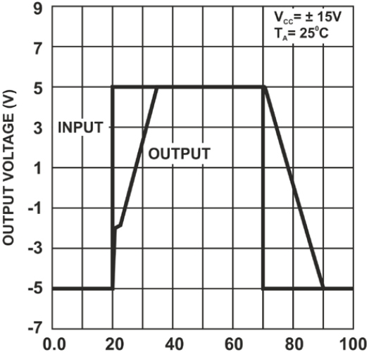
In this plot, it is clear that the output voltage slews with a fixed slope. The X-axis represents the time in µs, while the Y-axis represents voltage. Taking the falling edge, which starts at 70µs and ends at 90µs, which makes for a time difference of 20µs, and the voltage swing, which is 10V (from -5V to +5V) and using the above slew rate formula we can calculate the slew rate as,
Slew rate = dv/dt = 10v/20s = 0.5 /V/s
which corresponds perfectly with the value stated in the datasheet.
Commonly Asked Questions
What is the unit of slew rate?
The slew rate is typically measured in volts per microsecond (V/µs). This unit represents how quickly the output voltage of an op-amp can change in response to a rapid change in the input signal.
What causes slew rate limitation in an op-amp?
The slew rate limitation in an op-amp is primarily caused by the internal compensation capacitor, which is used to stabilize the op-amp and prevent oscillations. This capacitor, along with the internal circuitry, limits the rate at which the output voltage can change, as it determines how quickly the op-amp can charge or discharge its internal nodes. Other contributing factors include the finite gain-bandwidth product, the current limiting of the op-amp's output stage, and the load the op-amp is driving.
Why is the slew rate significant in op-amps?
The slew rate is significant because it determines how quickly an op-amp can respond to changes in the input signal. A high slew rate is essential for applications requiring fast response times, such as high-speed data acquisition, audio amplifiers, and video signal processing. It ensures that the op-amp can accurately reproduce the amplitude and phase of fast-changing signals, thereby preventing signal distortion, particularly in high-frequency applications.
Should the slew rate of an op-amp be higher or lower?
Whether an op-amp should have a higher or lower slew rate depends on the application. A higher slew rate is preferable for high-speed applications where the op-amp needs to accurately follow rapidly changing signals without introducing distortion. However, in applications where speed is not critical, a lower slew rate might be acceptable and can even be beneficial, as it can reduce the risk of unwanted oscillations and improve stability.
What is considered a normal slew rate for an op-amp?
A "normal" slew rate varies widely depending on the specific application and the op-amp design. For general-purpose op-amps, a slew rate in the range of 0.5 to 20 V/µs is common. However, for high-speed or precision applications, op-amps with slew rates exceeding 50 V/µs or even higher might be necessary. Conversely, for low-speed, precision applications, a slew rate as low as a few volts per microsecond or less might be sufficient. The specific requirements of the application will dictate the appropriate slew rate.
Applications of Slew Rate
Here are some key applications where the slew rate is particularly important:
- Audio Amplifiers: In audio applications, the slew rate is crucial for ensuring that the amplifier can accurately reproduce the input signal without distorting the high-frequency components. A higher slew rate allows the amplifier to handle rapid changes in the input signal, which is essential for high-fidelity audio reproduction, preventing issues like slew-induced distortion that can occur during fast transient signals.
- Data Conversion Systems: In analog-to-digital (A/D) and digital-to-analog (D/A) conversion systems, the slew rate affects the converter's ability to accurately track fast-changing input signals. A slow slew rate can introduce errors in the conversion process, leading to inaccuracies in the digitized output.
- Video Processing: Video signals, which have high-frequency components due to rapid changes in brightness and colour, require op-amps with high slew rates to avoid smearing or ghosting effects. An op-amp with an insufficient slew rate can result in distorted or blurred images.
- RF and High-Frequency Circuits: In radio frequency (RF) or high-speed circuits, the slew rate determines how quickly an op-amp can respond to fast-changing signals. This is crucial for modulating and demodulating signals, pulse shaping, and other high-speed signal processing tasks.
- Control Systems: In feedback and control systems, the slew rate affects the system's response time and stability. A slow slew rate can introduce phase lag, potentially leading to oscillations or degraded system performance, especially in fast-response systems like servo motors or active filters.
- Pulse Amplifiers: Op-amps are used in pulse amplifiers to shape and amplify pulses in digital circuits. The slew rate limits the speed at which the pulse can rise or fall, influencing the pulse width and the maximum achievable data rate.
- Filter Circuits: In active filter designs, the slew rate impacts the filter's ability to accurately follow the input signal, especially at high frequencies. A low slew rate can cause phase shift and amplitude distortion, particularly in filters designed for high-frequency signals.
- Oscillators: In oscillator circuits, the slew rate can influence the purity of the waveform. Insufficient slew rate leads to waveform distortion, affecting the harmonic content and stability of the oscillator.
- Medical Instrumentation: High-precision medical instruments, such as ECG or EEG monitors, require op-amps with adequate slew rates to accurately capture rapid changes in biological signals without introducing artifacts or distortions.
- Switching Power Supplies: In switching regulators and power supplies, op-amps help regulate the output voltage or current. The slew rate affects the speed at which the power supply can respond to load changes, impacting its overall performance and stability.
Slew Rate of Popular Op-Amps
| Op-Amp | Slew Rate (V/µs) | Remarks |
| LM741 | 0.5 | One of the most iconic op-amps, widely used in educational settings and basic analog circuits. |
| TL071 | 13 | A low-noise JFET-input op-amp, suitable for high-fidelity and audio applications. |
| LM324 | 0.5 | A popular quad op-amp, known for its operation from a single power supply and its wide use in consumer and industrial electronics. |
| LM358 | 0.3 | Dual op-amp, characterized by its low power consumption and wide range of supply voltages. |
| OP07 | 0.3 | Ultra-low offset voltage op-amp, used in applications requiring high precision. |
| RC4558 | 1.7 | Dual general-purpose operational amplifier. |
| LM833 | 7 | Dual audio op-amp, is commonly used in audio preamplifiers and mixers due to its excellent sound characteristics. |
| NE5532 | 9 | High-performance, low-noise op-amp, often employed in high-quality audio gear. |
| TL082 | 13 | JFET-input, high-speed op-amp, known for its low input bias and offset currents, is ideal for fast amplifiers in data acquisition systems. |
| CA3140 | 9 | MOSFET-input op-amp with a high slew rate, suitable for fast signal processing applications. |
| OPA2134 | 20 | High-speed FET-input op-amp, widely used in professional audio equipment, is noted for its low distortion and wide bandwidth. |


