nRF24L01 Wireless RF Module
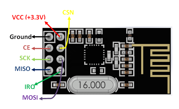
nRF24L01 Pinout Configuration
|
Pin Number |
Pin Name |
Abbreviation |
Function |
|
1 |
Ground |
Ground |
Connected to the Ground of the system |
|
2 |
Vcc |
Power |
Powers the module using 3.3V |
|
3 |
CE |
Chip Enable |
Used to enable SPI communication |
|
4 |
CSN |
Ship Select Not |
This pin has to be kept high always, else it will disable the SPI |
|
5 |
SCK |
Serial Clock |
Provides the clock pulse using which the SPI communication works |
|
6 |
MOSI |
Master Out Slave In |
Connected to MOSI pin of MCU, for the module to receive data from the MCU |
|
7 |
MISO |
Master In Slave Out |
Connected to MISO pin of MCU, for the module to send data from the MCU |
|
8 |
IRQ |
Interrupt |
It is an active low pin and is used only if interrupt is required |
nRF24L01 Features
- 2.4GHz RF transceiver Module
- Operating Voltage: 3.3V
- Nominal current: 50mA
- Range : 50 – 200 feet
- Operating current: 250mA (maximum)
- Communication Protocol: SPI
- Baud Rate: 250 kbps - 2 Mbps.
- Channel Range: 125
- Maximum Pipelines/node : 6
- Low cost wireless solution
Note: Complete Technical Details can be found at the NRF24L01 datasheet given at the end of this page.
Other RF modules
HC12, 433MhZ RF Module, nRF905
Other Wireless Options
Bluetooth, Lora, ESP8266, GSM, Xbee
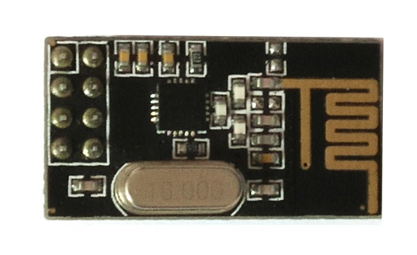
Brief Description on NRF24L01 RF Module
The nRF24L01 is a wireless transceiver module, meaning each module can both send as well as receive data. They operate in the frequency of 2.4GHz, which falls under the ISM band and hence it is legal to use in almost all countries for engineering applications. The modules when operated efficiently can cover a distance of 100 meters (200 feet) which makes it a great choice for all wireless remote controlled projects.
The module operates at 3.3V hence can be easily used with 3.2V systems or 5V systems. Each module has an address range of 125 and each module can communicate with 6 other modules hence it is possible to have multiple wireless units communicating with each other in a particular area. Hence mesh networks or other types of networks are possible using this module. So if you are looking for a wireless module with the above properties then this module would be an ideal choice for you.
How to Use the NRF24L01 Module
The NRF24L01 module works with the help of SPI communications. These modules can either be used with a 3.3V microcontroller or a 5V microcontroller but it should have an SPI port. The complete details on how to use the module through SPI is given the data sheet below. The circuit diagram shows how the module should be interfaced with a microcontroller.
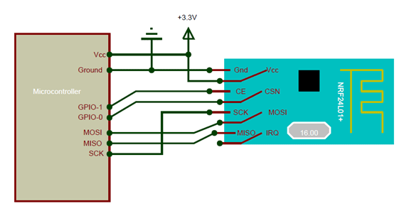
Here I have shown how for a 3.3V microcontroller, but it applies the same for a 5V MCU as well. The SPI Pins (MISO<MOSI and SCK) are connected to the SPI pins of the Microcontroller and the signal pins (CE and CSN) are connected to the GPIO pins of the MCU.
If you are interfacing the module with Arduino, then there are ready made libraries available like the R24 Library. With the help of these libraries you can easily interface the nRF24L01 with Arduino with few lines of code. If you are using for some other microcontroller then you have to read through the datasheet to understand how to establish the SPI communication.
The nRF24L01 module is a bit tricky to use especially since there are many cloned versions in the market. If you are having any problem with getting it work, try adding a 10uF and 0.1uF capacitor in parallel to the Vcc and Ground pins. Also make sure the 3.3V supply is clean and does not have any noise coupled in it.
Applications
- Wireless Control application
- Mesh Networks
- RF Remote Controllers
- Connected devices
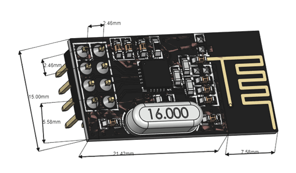
2D –Model