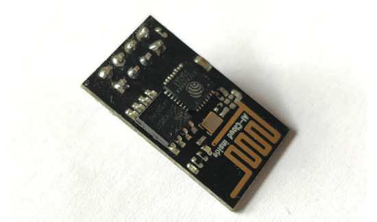
ESP8266 - WiFi Module
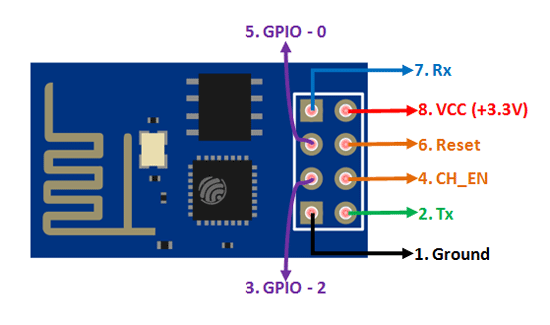
ESP8266 Pin Configuration
|
Pin Number |
Pin Name |
Alternate Name |
Normally used for |
Alternate purpose |
|
1 |
Ground |
- |
Connected to the ground of the circuit |
- |
|
2 |
TX |
GPIO – 1 |
Connected to Rx pin of programmer/uC to upload program |
Can act as a General purpose Input/output pin when not used as TX |
|
3 |
GPIO-2 |
- |
General purpose Input/output pin |
- |
|
4 |
CH_EN |
- |
Chip Enable – Active high |
- |
|
5 |
GPIO - 0 |
Flash |
General purpose Input/output pin |
Takes module into serial programming when held low during start up |
|
6 |
Reset |
- |
Resets the module |
- |
|
7 |
RX |
GPIO - 3 |
General purpose Input/output pin |
Can act as a General purpose Input/output pin when not used as RX |
|
8 |
Vcc |
- |
Connect to +3.3V only |
|
ESP8266-01 Features
- Low cost, compact and powerful Wi-Fi Module
- Power Supply: +3.3V only
- Current Consumption: 100mA
- I/O Voltage: 3.6V (max)
- I/O source current: 12mA (max)
- Built-in low power 32-bit MCU @ 80MHz
- 512kB Flash Memory
- Can be used as Station or Access Point or both combined
- Supports Deep sleep (<10uA)
- Supports serial communication hence compatible with many development platform like Arduino
- Can be programmed using Arduino IDE or AT-commands or Lua Script
ESP8266 Equivalents
ESP-12 (Has more GPIO pins that support ADC, PWM, SPI etc)
Alternative for ESP8266-01
ESP32 (more powerful and standalone module)
ESP8266-01 Boot Option
|
GPIO – 0 |
GPIO – 2 |
Mode |
Used For |
|
High |
High |
Flash Mode |
Run the program that is already uploaded to the module |
|
Low |
High |
UART Mode |
Programming mode- to program using Arduino or any serial communication |
Where to use ESP8266-01
The ESP8266 is a very user friendly and low cost device to provide internet connectivity to your projects. The module can work both as a Access point (can create hotspot) and as a station (can connect to Wi-Fi), hence it can easily fetch data and upload it to the internet making Internet of Things as easy as possible. It can also fetch data from internet using API’s hence your project could access any information that is available in the internet, thus making it smarter. Another exciting feature of this module is that it can be programmed using the Arduino IDE which makes it a lot more user friendly. However this version of the module has only 2 GPIO pins (you can hack it to use upto 4) so you have to use it along with another microcontroller like Arduino, else you can look onto the more standalone ESP-12 or ESP-32 versions. So if you are looking for a module to get started with IOT or to provide internet connectivity to your project then this module is the right choice for you.
How to use the ESP8266 Module
There are so many methods and IDEs available to with ESP modules, but the most commonly used on is the Arduino IDE. So let us discuss only about that further below.
The ESP8266 module works with 3.3V only, anything more than 3.7V would kill the module hence be cautions with your circuits. The best way to program an ESP-01 is by using the FTDI board that supports 3.3V programming. If you don’t have one it is recommended to buy one or for time being you can also use an Arduino board. One commonly problem that every one faces with ESP-01 is the powering up problem. The module is a bit power hungry while programming and hence you can power it with a 3.3V pin on Arduino or just use a potential divider. So it is important to make a small voltage regulator for 3.31v that could supply a minimum of 500mA. One recommended regulator is the LM317 which could handle the job easily. A simplified circuit diagram for using the ESP8266-01 module is given below
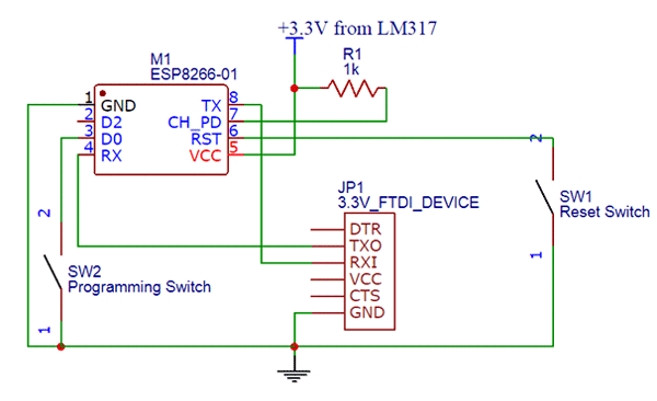
The switch SW2 (Programming Switch) should be held pressed to hold the GPIO-0 pin to ground. This way we can enter into the programming mode and upload the code. Once the code is released the switch can be released.
Applications
- IOT Projects
- Access Point Portals
- Wireless Data logging
- Smart Home Automation
- Learn basics of networking
- Portable Electronics
- Smart bulbs and Sockets
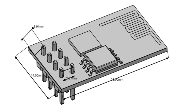
2D – Model


<a href="https://gotwebsite1.com/local-seo-phoenix/">Unveiling t