PCR406 Sensitive Gate Thyristor
PCR406 Features and Specifications
- Blocking voltage to 600 V
- High performance planner diffused PNPN devices
- On-state RMS current is 0.8 A
- Repetitive peak off-state voltage is 400 V
- Ultra-low gate triggering gate current: 200uA
- Triggering gate voltage: 0.8V
- Maximum peak reverse gate voltage: 1v
- Peak gate current: 0.1A
- Holding current: 5mA
- Latching current: 6mA
- Operating temperature range: - 40 to + 125 °C
- Storage temperature: - 40 to + 150 °C
PCR406 Equivalent Thyristors
MCR100-6G
Where to Use PCR406 Thyristor?
Thyristor is a switching device but can be used in power control circuit, over-voltage protection, and many other applications. It requires a gate pulse to start, it gets self-latched and stays ON until the supply get interrupted. For this, we have to use a switching circuit in connection with the main supply of the circuit or across the thyristor to turn it OFF. UTC PCR406 silicon controlled rectifiers are high performance planner diffused PNPN devices, with a Repetitive peak off-state voltage value of 400 V and On-state RMS current of 0.8 A. Fit for various modes of control like motor control circuit, inrush current limiting circuits, capacitive discharge ignition and voltage regulation circuits.
How to Use PCR406 Thyristor?
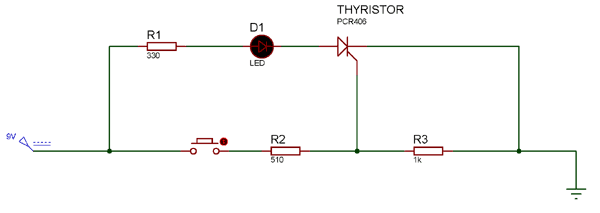
Initially, the switch S1 and S2 remains in normally-open state. When the supply ON, Thyristor remain reversed biased until the gate pulse provided. For providing gate pulse we have used Push Button S2. As the S2 switch close, thyristor turns ON and latch even we release the push button S2.
When the Thyristor has self-latched into the ON state, the only way to stop the Thyristor from conducting in this circuit is to interrupt the supply across the Thyristor. For that, we use switch S1, which short-circuit the anode and cathode, due to which the holding current get decreased to its threshold value. Therefore, Thyristor gets reset or turns OFF.
Resistance R1 used to provide sufficient gate current to turn ON the thyristor. Resistance R2 is used for decreasing the gate sensitivity and increase the dv/dt capability. Therefore, it prevents Thyristor from false triggering.
Applications
- Power Control
- Motor Control
- Heating
- Industrial and Domestic lighting
- Static Switching
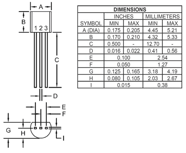
2D-model and Dimensions