5V 8-Channel Relay Module
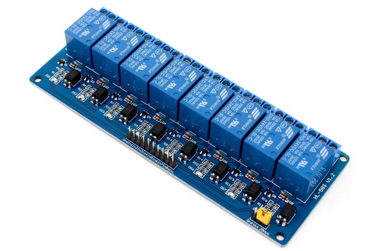
The eight-channel relay module contains eight 5V relays and the associated switching and isolating components, which makes interfacing with a microcontroller or sensor easy with minimum components and connections. Each relay on the board has the same circuit, and the input ground is common to all eight channels.
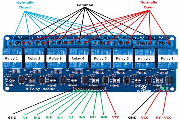
Eight-Channel Relay Module Pinout
|
Pin Number |
Pin Name |
Description |
|
1 |
GND |
Ground reference for the module |
|
2 |
IN1 |
Input to activate relay 1 |
|
3 |
IN2 |
Input to activate relay 2 |
|
4 |
IN3 |
Input to activate relay 3 |
|
5 |
IN4 |
Input to activate relay 4 |
|
6 |
IN5 |
Input to activate relay 5 |
|
7 |
IN6 |
Input to activate relay 6 |
|
8 |
IN7 |
Input to activate relay 7 |
|
9 |
IN8 |
Input to activate relay 8 |
|
10 |
VCC |
Power supply for the relay module |
|
11 |
GND |
Ground reference for the module |
|
12 |
VCC |
Power supply selection jumper |
|
13 |
RY-VCC |
Alternate power pin for the relay module |
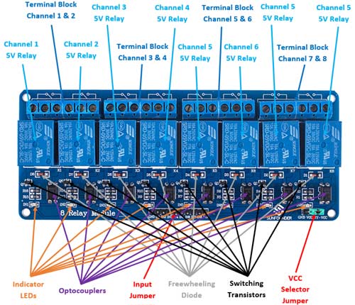
Components Present on an Eight-Channel Relay Module
The following are the major components present on the eight-channel relay module, which will be described in detail later in the article.
5V relay, terminal blocks, male headers, transistors, optocouplers, diodes, and LEDs.
Eight-Channel Relay Module Specifications
- Supply voltage – 3.75V to 6V
- Trigger current – 5mA
- Current when relay is active - ~70mA (single), ~600mA (all eight)
- Relay maximum contact voltage – 250VAC, 30VDC
- Relay maximum current – 10A
Alternate Relay Modules
Single-channel relay module, dual-channel relay module, four-channel relay module.
Alternate Modules
SCRs, TRIACs, Solid State Relay module.
Understanding 5V Eight-Channel Relay Module
The eight-channel relay module contains eight 5V relays and the associated switching and isolating components, which makes interfacing with a microcontroller or sensor easy with minimum components and connections. There are eight terminal blocks with six terminals each, and each block is shared by two relays. The terminals are screw type, which makes connections to mains wiring easy and changeable.
The eight relays on the module are rated for 5V, which means the relay is activated when there is approximately 5V across the coil. The contacts on each relay are specified for 250VAC and 30VDC and 10A in each case, as marked on the body of the relays. The switching transistors act as a buffer between the relay coils that require high currents, and the inputs which don’t draw much current. They amplify the input signal so that they can drive the coils to activate the relays.
The freewheeling diodes prevent voltage spikes across the transistors when the relay is turned off since the coils are an inductive load. The indicator LEDs glow when the coil of the respective relay is energized, indicating that the relay is active.
The optocouplers form an additional layer of isolation between the load being switched and the inputs. The isolation is optional and can be selected using the VCC selector jumper. The input jumper contains the main VCC, GND, and input pins for easy connection using female jumper wires.
Internal Circuit Diagram for Eight-Channel Relay Module
The circuit on the board is as follows:
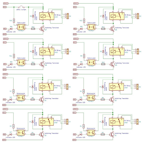
Each relay on the board has the same circuit, and the input ground is common to all eight channels.
The driver circuit for this relay module is slightly different compared to traditional relay driving circuits since there is an optional additional layer of isolation. When the jumper is shorted, the relay and the input share the same VCC, and when it is open, a separated power supply must be provided to the JD-VCC jumper to power the relay coil and optocoupler output.
The inputs for this module are active low, meaning that the relay is activated when the signal on the input header is low. This is because the indicator LED and the input of the optocoupler is connected in series to the VCC pin on one end, so the other end must be connected to the ground to enable the current flow. The optocoupler used here is the PCF817, which is a common optocoupler that can also be found in through-hole packaging.
How to Use the Eight-Channel Relay Module
The eight-channel can be used to switch multiple loads at the same time since there are eight relays on the same module. This is useful in creating a central hub from where multiple remote loads can be powered, which is useful for tasks like home automation where the module can be placed in the main switchboard and can be connected to loads in other parts of the house and can be controlled from a central location using a microcontroller.
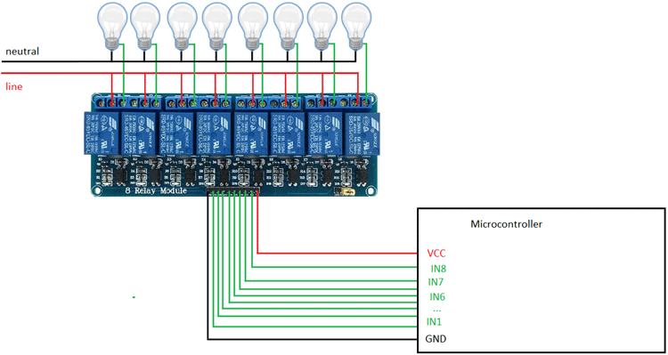
In this diagram, eight separate loads (represented by lightbulbs) have been connected to the NO terminals of the relay. The live wire has been connected to the common terminal of each relay. When the relays are activated, the load is connected to the live wire and is powered. This setup can be reversed by connecting the load to the NC terminal, which will keep it powered on till the relay is activated.
Eight-Channel Relay Module Basic Troubleshooting
If either of the relays does not turn on:
- The contacts might be welded due to overcurrent/arcing. Shaking the module firmly might help unstick the contacts.
- The driver circuitry might have been damaged due to overvoltage.
- Input polarity might be incorrect.
- Jumper might not have been moved to the correct position
Eight-Channel Relay Module Applications
- Switching mains loads
- Home automation
- Battery backup
- High current load switching


