12V Relay Switch


Relay Pinout Configuration
|
Pin Number |
Pin Name |
Description |
|
1 |
Coil End 1 |
Used to trigger(On/Off) the Relay, Normally one end is connected to 12V and the other end to ground |
|
2 |
Coil End 2 |
Used to trigger(On/Off) the Relay, Normally one end is connected to 12V and the other end to ground |
|
3 |
Common (COM) |
Common is connected to one End of the Load that is to be controlled |
|
4 |
Normally Close (NC) |
The other end of the load is either connected to NO or NC. If connected to NC the load remains connected before trigger |
|
5 |
Normally Open (NO) |
The other end of the load is either connected to NO or NC. If connected to NO the load remains disconnected before trigger |
Note: Complete technical details can be found in the Relay Datasheet linked at the bottom of this page.
Equivalent Relays
3V Relay, 5V Relay, 1-channel Relay module, 4-channel Relay Module
How to Use a Relay?
Relays are most commonly used switching device in electronics. There are two important parameters of relay, first is the Trigger Voltage, this is the voltage required to turn on the relay that is to change the contact from Common → NC to Common → NO. The other parameter is your Load Voltage & Current, this is the amount of voltage or current that the NC, NO or Common terminal of the relay could withstand, in our case for DC it is maximum of 30V and 10A. Make sure the load you are using falls into this range.
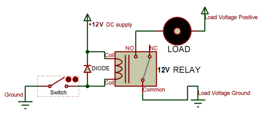
The above diagram is for relay triggering circuit. Since the relay has 12V trigger voltage we have used a +12V DC supply to one end of the coil and the other end to ground through a switch. For switching we are using a transistor as a switching device. You can also notice a diode connected across the coil of the relay, this diode is called the Fly back Diode. The purpose of the diode is to protect the switch from high voltage spike that can produced by the relay coil. As shown one end of the load can be connected to the Common pin and the other end is either connected to NO or NC. If connected to NO the load remains disconnected before trigger and if connected to NC the load remains connected before trigger.
Applications
- Commonly used in switching circuits.
- For Home Automation projects to switch AC loads
- To Control (On/Off) Heavy loads at a pre-determined time/condition
- Used in safety circuits to disconnect the load from supply in event of failure
- Used in Automobiles electronics for controlling indicators glass motors etc.
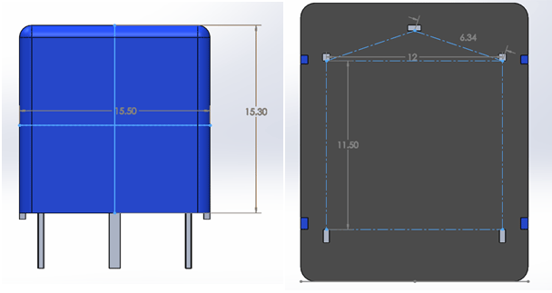
2D-Model and Dimensions