AD9850 DDS Signal Generator Module
The AD9850 DDS Signal Generator Module provides 0-40MHz sine and square waves. It is equipped with a powerful 125Mhz Oscillator and excellent for a signal generator and oscilloscope based DIY projects.
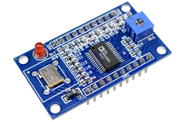
The module has a small compact size of approx 4.5×2.6×1.7 cm. In such a small size, the module can be fitted in any DIY based signal generation projects. It has two square wave channels and two sine wave channels. It can work from 3.3V to the 5V input voltage.
Pin Description
|
Pin Name |
Description |
|
VCC |
This is a voltage supply pin. 3.3V or 5V power input |
|
GND |
GND Pin. |
|
W_CLK |
Frequency Update. On the rising edge of this clock, the DDS will update to the frequency (or phase) loaded in the data input register, it then resets the pointer to Word 0 |
|
DATA |
D7, Serial Load |
|
RESET |
Reset. This is the master reset function; when set high, it clears all registers (except the input register) and the DAC output will go to Cosine 0 after additional clock cycles |
|
D0–D7 |
8-Bit Data Input. This is the 8-bit data port for iteratively loading the 32-bit frequency and 8-bit phase/28–25 control word. D7 = MSB; D0 = LSB. D7 (Pin 25) also serves as the input pin for the 40-bit serial data word. |
|
Square Wave Output 1 |
This is the comparator’s true output |
|
Square Wave Output 2 |
This is the comparator’s complement output. |
|
Sine Wave Output 1 |
Analog Current Output of the DAC. |
|
Sine Wave Output 2 |
The Complementary Analog Output of the DAC. |
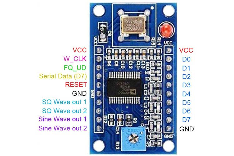
The pinout can be easily seen in the image below.
Features
- AD9850 signal generator modules supply voltage: 6
- Operating Voltage Range: 3.3V - 5V
- Output Frequency Range: 0-40MHz
- Digital Output Continuous Current(A): 0.005
- DAC Output Current: 0.03
- Storage Condition: -40~ +80°C
- Operating Temperature Range: -40~ +85°C
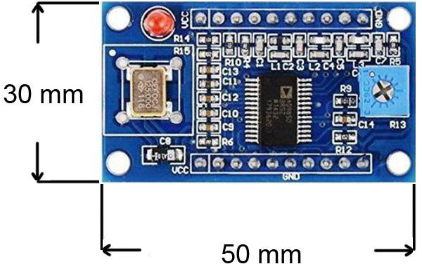
- Dimensions: (50*30*20mm) L×W*H
Note: Complete technical details can be found in the AD9850 Datasheet linked at the bottom of this page.
Alternative Products
Replacement of this AD9850 Based Signal Generator Module Board -
- ICL8038 Signal Generator module
- AD9833 Function Generator module
AD9850 Based DDS Signal Generator Module Board - Overview
The main driver IC is AD9850.
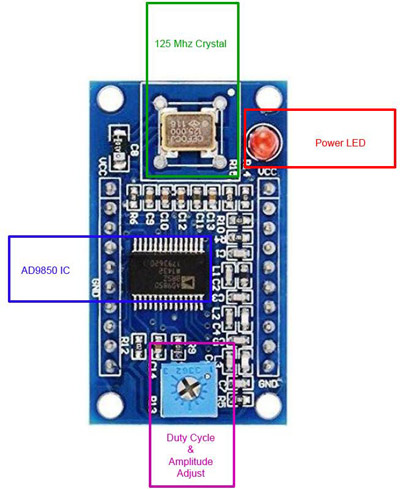
Equipped with a powerful 125 MHz oscillator, from 3.3V to 5V input voltage, the function generator could produce 0-40 Mhz of output waves where two outputs are specified for sine waves and two outputs are specified for square wave output.
The module also has a power indicator LED that can be useful for the user to get notified about the power availability status.
The output Amplitude and the Duty Cycle is adjustable using a Potentiometer that is available in the module.
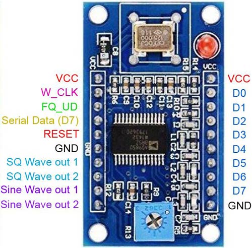
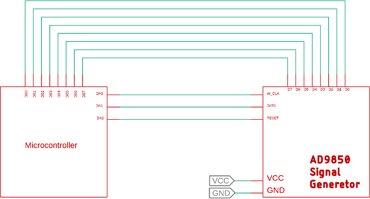
Interfacing Diagram
The interfacing of the AD9850 module is quite easy. Follow the below image to connect the AD9850 module. It requires 8-bit parallel interfacing along with 3 additional pins W_CLK, FU_UD, and for the RESET pins.
Any microcontrollers can be used to interface with the AD9850 module.
Applications
- Signal Generation related work.
- Oscilloscope based function generator
2D Model
The dimensions of the AD9850 Function Generator is shown below-