STM32 Nucleo F401RE Development Board
The STM32 Nucleo boards are the official Development Boards from STMicroelectronics. It features the ARM Cortex M4 32-bit STM32F401RET6 microcontroller which is in LQFP64 package. The Boards pinout is similar to Arduino UNO and has many other additional pins to expand performance. This board also comes with an integrated ST-LINK/V2-1 programmer and debugger; hence it is very easy to get started with this board.
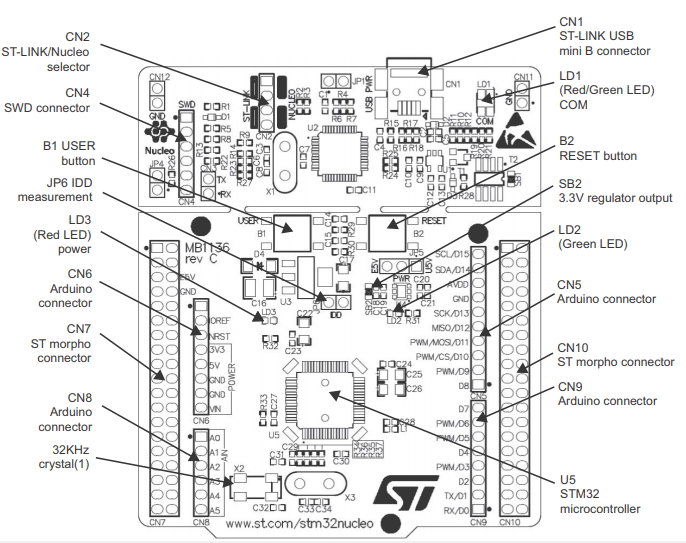
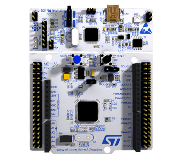
As shown in the image above, there are three LEDs, where LD1 is for indicating USB communication, LD2 is programmable LED, and LD3 indicates power. Similarly, there are two push buttons where one is user programmable, and the other is to reset the Microcontroller. The Board operates with 3.3V supply but a wide voltage range of 7-12V can be provided to the VIN pin since it has an on-board voltage regulator.
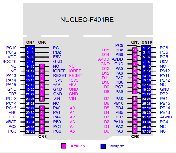
Nucleo-F401RE Pinout Configuration
The STM32 Nucleo board pinout is shown above. As you can see, there are two sets of pins. The pin one resembles the Arduino UNO and the blue one is the STM32 style (Morpho). The arduino like pins are female connector pins which exactly match the order and position of Arduino UNO pins and hence any Arduino shield can be used with these development boards.
The Arduino pins are split into category CN5, CN6, CN8, and CN9. Each category pin can be tabulated as follows:
|
Pin Category |
Pin Type |
Pin names |
Description |
|
CN6 |
Power |
IOREF |
3.3V Reference Voltage pin |
|
RESET |
Resets the Microcontroller |
||
|
+3.3V |
Provides 3.3V as output can also be used to power the MCU |
||
|
+5V |
5V output only pin |
||
|
GND |
Ground pins |
||
|
CN8 |
Analog Pins and I2C |
A0-A1 |
Used to measure Analog Voltage |
|
A4 and A5 |
These pins can also be used for I2C Communication A4 is SDA and A5 is SCL |
||
|
CN5 |
Digital Pins and SPI |
D8-D15 |
Digital GPIO pins |
|
AVDD |
Can be used to provide analog reference voltage |
||
|
GND |
Ground Pins |
||
|
D13, D12. D11 and D10 |
Acts as SCK, MISO, MOSI and CS pins respectively for SPI communication |
||
|
CN9 |
Digital Pins and USART |
D0 to D7 |
Digital GPIO pins |
|
D0 and D1 |
Acts as Rx and Tx pins respectively for USART communication |
Apart from the Arduino pins, the board also has 76 (38+38) GPIO pins as male headers on either side of the board as shown above. These pins are classified into CN7 and CN10 with each having 38 Pins. They comprise of GPIO pins, Analog Pins, Timer Pins, and Power pins. The name of the pins can be found in the image above. They are also categorized with the table below:
|
Pin Category |
Pin Type |
Pin names |
Description |
|
CN7 |
Port pins |
PC0, PC1, PC2, PC3, PC10, PC11, PC12, PC13, PC14, PC15 |
Port C digital I/O pins |
|
PD2 |
Port D I/O pin |
||
|
PA0, PA1, PA4, PA13, PA14, PA15 |
Port A I/O pins |
||
|
PB7, PB8 and PB9 |
Port B I/O pin |
||
|
PH0 and PH1 |
Port H I/O pins |
||
|
Power |
VBAT |
Can be used to power them module from battery |
|
|
+3.3V |
Provides 3.3V as output can also be used to power the MCU |
||
|
+5V |
5V output only pin |
||
|
VIN |
Unregulated input power pin |
||
|
RESET |
Resets the MCU |
||
|
IOREF |
Reference Voltage Pin |
||
|
CN10 |
Port Pins |
PC4, PC5, PC6, PC7, PC8, PC9 |
Port C I/O Pins |
|
PA2, PA3, PA4, PA6, PA7, PA10, PA11 and PA12 |
Port A I/O Pins |
||
|
PB1, PB2, PB3, PB4, PB5, PB6, PB8, PB9, PB10, PB12, PB14, PB15 |
Port B I/O Pins |
||
|
Power |
U5V |
5V Power Pin |
|
|
GND |
System Ground of the MCU |
||
|
AGND |
Analog Ground Pin |
Technical Specifications
|
Microcontroller |
STM32F401RET6 (32-bit) |
|
Architecture |
ARM Cortex M4 CPU with FPU |
|
Power consumption |
2.4uA at standby without RTC |
|
CPU Frequency |
84 MHz |
|
Crystal Oscillator Range |
4 to 26 MHz |
|
MCU Operating Voltage (VDD) |
1.7V to 3.6V |
|
Board Operating Voltage (VIN) |
7V to 15V |
|
Flash Memory |
512KB |
|
SRAM |
96 KB |
|
GPIO Pins |
50 |
|
ADC |
12-bit 16Channel |
|
RTC |
In-built 32kHz with calibration |
|
Timers |
16-bit (6) 32-bit (2) |
|
Watchdog Timers |
2 |
|
USART/UART Communication |
4 |
|
I2C Communication |
3 |
|
SPI Communication |
3 |
|
USB2.0 Support |
Yes |
|
Internal Crystal Oscillator |
Yes, 16MHz |
|
On Board Debugger |
Yes, Serial Wire and JTAG |
Note: More technical information can be found in the STM32 Nucleo-F401RE Datasheet, linked at the bottom of this page.
Other Development Boards
Arduino UNO, Arduino Pro Mini, Arduino Mega, Arduino Due, Arduino Leonardo, Raspberry Pi, PIC Development Board, AVR Development Board, MSP430 Launchpad, Intel Edison, ESP32
How to Program STM32 Nucleo Boards
The Nucleo Development Board is relatively easy to get started and learn since it has an in-built programmer and debugger. The Board can be programmed with many Development tool chains which are listed below:
- Keil MDK-ARM
- IAR Workbench
- GCC based IDE
- ARM Mbed (online)
Out of these, the Keil MDK is the most used one. It is beginner friendly and on top of that, it is free to use, just download the IDE and its respective drive from link below.
Software: Keil MDK Version 5
Driver: Nucleo USB Driver
Applications
The STM32 MCUs are commonly used in many industrial and commercial products these days. Some specific application include-
- Low Power portable Electronics
- Robotics
- System Automation
- IOT
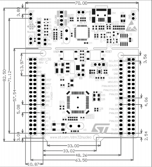
2D Model and Dimensions