4N28 Optocoupler IC
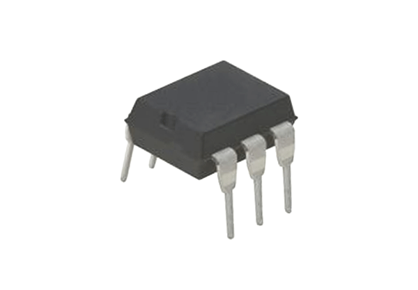
The 4N28 is an Industry Standard Single Channel Phototransistor Coupler. This family includes the 4N25, 4N26, 4N27 and 4N28. Each OPTOCOUPLER consists of gallium arsenide infrared LED and a silicon NPN phototransistor. In the chip the primary circuit and secondary circuit are isolated electrically. The pair of diode and phototransistor is there to provide optical trigger mechanism between the primary and secondary circuit.
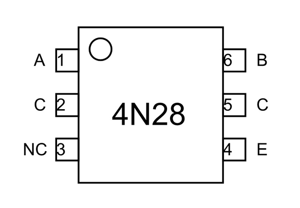
4N28 Pinout Configuration
4N28 is a six pin IC which is available in various packages. Basically we use only four pins in the chip but can use up to five pins. The internal connections of diode and photo transistor are described below.
|
Pin Number |
Pin Name |
Description |
|
1 |
Anode (A) |
Positive terminal of internal IR LED |
|
2 |
Cathode (C) |
Negative terminal of internal IR LED |
|
3 |
NC |
No Connection |
|
4 |
Emitter (E) |
Emitter of internal PHOTO TRANSISTOR |
|
5 |
Collector (C) |
Collector of internal PHOTO TRANSISTOR |
|
6 |
Base (B) |
Base of internal PHOTO TRANSISTOR |
Features and Specifications
- Interfaces with common logic families
- Isolation test voltage 5000VRMS
- Input-Output coupling capacitance < 0.5pF
- Input-Output isolation voltage: 500VRMS
- IR LED Forward Voltage for turning ON: 1.2V-1.5V (Typically 1.3V, 1.5V being absolute maximum forward voltage)
- IR LED Forward Current during ON (IF): 10mA - 80mA (Typically 10mA, 80mA being absolute maximum forward current)
- IR LED MaximumReverse Voltage: 6V
- IR LED Maximum Reverse Current: 10uA
- Maximum voltage across COLLECTOR and EMITTER of PHOTO TRANSISTOR: 70V
- Maximum current allowed trough TRANSISTOR COLLECTOR(IC): 100mA
- Current Transfer Ration (CTR): 10%
- Typical Rise Time: 3us
- Typical Fall Time: 3us
- No additional power needed to be applied for chip for making it work.
Note: Complete technical details can be found in the 4N28 Datasheet linked at the bottom of this page.
4N28 Equivalents
4N28 OPTOCOUPLER IC has many replacements like 4N26, 4N27, 4N25, 4N33, MCT2E, etc. We do need to check on electrical parameters before replacing. Replacing without taking voltage, current and frequency parameters may lead to permanent damage to your circuit.
Overview of 4N28 OPTOCOUPLER
The OPTOCOUPLER is basically used when you want to isolate two circuits electrically but still want to have a direct control mechanism. Say you want to control a small DC motor by using MICROCONTROLLER output. But you cannot connect the DC motor directly to the MICROCONTROLLER as it is a sensitive device. So for isolating load circuit and protecting the MICROCONTROLLER from voltage fluctuations, we can use 4N28 OPTOCOUPLER.
How to use 4N28 OPTOCOUPLER
As described in pin diagram, the chip has two components. They are IR Diode and Photo Transistor. The IR DIODE is connected between terminals 1 and 2.The PHOTOTRANSISTOR is connected at terminals 4, 5 and 6. We will connect chip with other few components to form an example circuit.
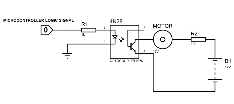
As shown in above circuit, the chip gets trigger pulses from microcontroller and they act as INPUT. And a MOTOR is connected at the collector to work as OUTPUT.
At the INPUT we will get the +3.3V logic signal from a microcontroller. Since the pin represents POSITIVE of IR DIODE, it will get powered. Once powered, the IR DIODE will emit Infrared rays internally. These rays will fall on the PHOTOTRANSISTOR to gets it turned ON. When transistor gets turned ON the current flows through load circuit and a voltage will appear across the motor. Thus the motor rotates when microcontroller provides HIGH logic to the chip at the INPUT.
When the microcontroller trigger goes LOW, the IR DIODE input goes LOW. Since no power is provided the IR DIODE stops emitting radiation. Once radiation is absent the PHOTOTRANSISTOR gets turned OFF.And the transistor jumps from LOW RESISTANCE state to HIGH RESISTANCE state. With HIGH RESISTANCE the complete supply voltage appears across the transistor and current flow in the load circuit gets ZERO. So the motor stops rotating. Thus the motor stops rotating when the microcontroller provides LOW logic to the chip at the INPUT.
In the circuit, the MOTOR- PHOTOTRANSISTOR act as LOAD CIRCUIT and MCROCONTROLLER-IR DIODE act as a TRIGGER CIRCUIT. You can see the motor draws power from the +12V battery source and not from the trigger circuit. And PHOTOTRANSISTOR side secondary circuit here is in complete isolation with the IR DIODE primary circuit. So we have achieved the objective of isolating the two circuits using OPTOCOUPLER.
Applications
- Circuit isolation
- DC motor speed control
- Lighting systems
- PWM applications
- AC mains detection
- Reed relay driving
- Switch mode power supply feedback
- Telephone ring detection
- Logic ground isolation
- 10. Logic coupling with high frequency noise rejection
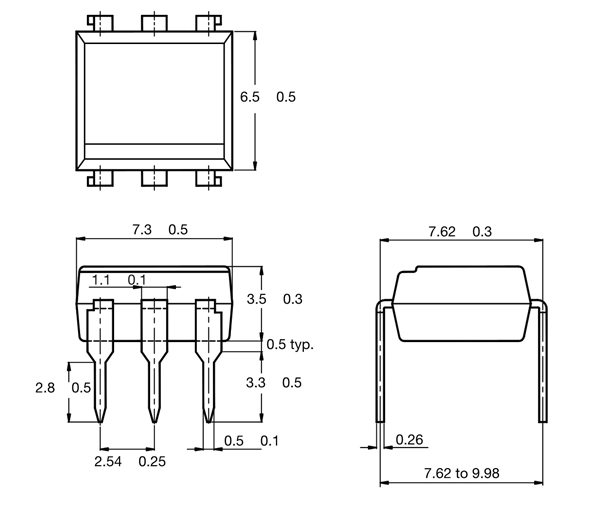
2D-Model and Dimensions
All measurements are in millimeter