Micro B USB Jack
Pin Configuration
|
Pin No. |
Pin Name |
Connected to wire color |
Description |
|
1 |
Vcc (+5V) |
Red |
+5V DC voltage |
|
2 |
D- |
White |
Data - |
|
3 |
D+ |
Green |
Data + |
|
4 |
ID |
Blue |
Mode detect |
|
5 |
Gnd |
Black |
Ground |
Specifications
- Micro USB – Type B/SMT
- Gender: Female
- Number of Pins: 5
- Mating cycle : More than 5000 times
- Current rating: 1A
- Voltage Rating: 30V (max)
- Contact resistance: 30mΩ @ 100mA
- Available as standard, drop in and reverse mount
Where to use micro USB
The micro USB jack finds its applications in many embedded projects where serial communication or power supply is required. It can be commonly found on Mobiles phones as charging/communication ports. Similarly it is used for the same purpose on raspberry pi, ESP modules and much more. These sockets have 5 pins, out which is two is used for power supply and other two is used for data communication. This data communication can receive data from any other MCU/MPU or even a computer or mobile phone. So if you are looking for an USB option on your project which occupies less space, this might be the right choice for you.
How to use micro USB
The micro USB connector can be used to power or communicate with devices. The maximum current that can be handled by this connector is 1A. However it is recommended not use loads more than 500mA for USB connectors as per USB consortium.
The micro USB Jack has five pins through which the power and data is transferred, the 4th pin ID is used for mode detection, this indicates if the USB is used only for power or for data transfer. Of the remaining four pins two pins (pin 1 and Pin 5) are used to provide the Vcc and Ground. The supply voltage of Vcc is +5V and is usually provided from the Microcontroller itself. The ground pin is connected to the ground of microcontroller.
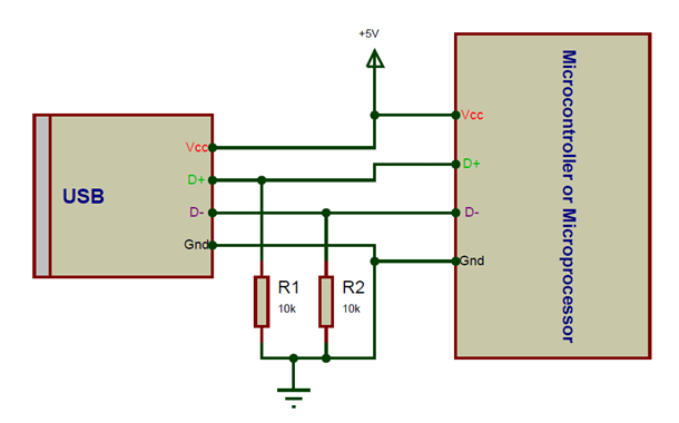
The remaining two pins are the D+ and the D-. These pins should be connected to the D+ and D- pins of the host respectively. They also require a pull-down resistor of value 15K each for the data to transfer. A sample connection set-up is shown below.
Applications
- Charging portable batteries
- Battery management systems
- Serial Bus connections
- Portable and pluggable devices
- Small distance, high speed communication
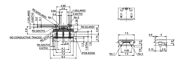
2D Model