UCC25600 Resonant Mode Controller
The UCC25600 is an 8-pin high performance, resonant mode controller specially designed for dc-to-dc applications using resonant topologies, especially the LLC half-bridge resonant converter. This IC provides complete system protection functions including overcurrent, UVLO, bias supply OVP, and over-temperature protection.
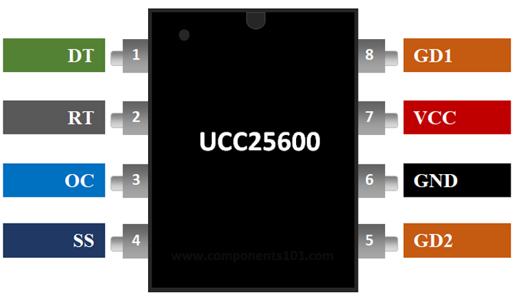
Pin Configuration of UCC25600
|
Pin Number |
Pin Name |
Description |
|
1 |
DT (Dead Time) |
This pin sets the dead time of high-side and low-side switch driving signals |
|
2 |
RT |
The current flowing out of this pin sets the frequency of the gate driver signals. |
|
3 |
OC |
Overcurrent protection pin |
|
4 |
SS |
Soft-start Pin. This pin sets the soft-start time of the system |
|
5, 8 |
GD2, GD1 |
High-side and low-side switch gate driver |
|
6 |
GND |
Ground Pin |
|
7 |
VCC |
Power Supply Pin |
Features & Specifications of UCC25600
- Number of Outputs: 2 Output
- Switching Frequency: 350 kHz
- Duty Cycle - Max: 50 %
- Voltage - Supply (Vcc/Vdd) 11.5V ~ 18V
- Output Voltage: - 0.5 V to 22.5 V
- Output Current: 800 mA
- Bias Voltage UVLO and Overvoltage Protection
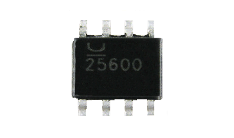
- Available in SOIC 8-Pin Package
Note: Complete Technical Details can be found at the UCC25600 datasheet given at the end of this page.
UCC25600 Equivalent
ACT4514, CS51411, TS2580
Alternative DC-DC Controllers
MC34063A, LM2596, MCP16252, TC7660
Where to use UCC25600 IC
The UCC25600 is a resonant mode controller IC, which is normally used for dc-to-dc applications. It is an industrial standard IC and can be found in adapters and home audio systems. Since the regulation occurs through switching it is very efficient than linear circuits. The internal oscillator supports the switching frequencies from 40 kHz to 350 kHz.
The input voltage for the IC is from 11.5V to 18V and the output voltage can be varied from 0.5V to 22.5V and the maximum output current can be up to 800mA. So if you looking to design a DC-DC converter with the above specifications then UCC25600 might be of interest to you.
How to use UCC25600 IC
The IC requires a minimum number of components to be operational. A test circuit diagram from the UCC25600 datasheet is given below. Pin 1 is connected to ground through a resistor. This pin sets the dead time of high-side and low-side switch driving signals. The collector pin of an optocoupler is connected to pin 2 of IC to control the switching frequency for regulation purposes.
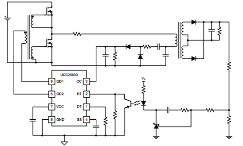
Pin 3 is for overcurrent protection. When the voltage on this pin is above 1 V, gate driver signals are actively pulled low. After the voltage falls below 0.6 V, the gate driver signal recovers with a soft-start. Pin 5 and 8 are connected to the primary side of the gate driver transformer to drive the half-bridge.
Applications of UCC25600
- 100-W to 1-kW Power Supplies
- LCD, Plasma, and DLP® TVs
- Adaptors, Computing, and ATX Power Supplies
- Home Audio Systems
- Electronic Lighting Ballasts
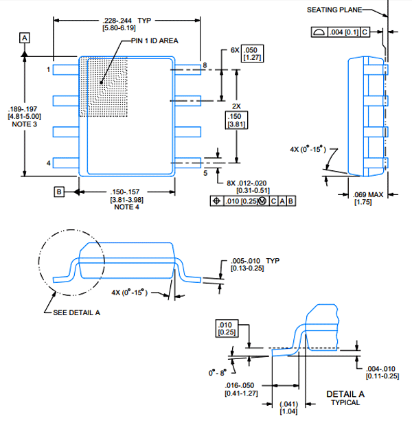
2D Model of UCC25600
Dimensions for UCC25600 IC is given below. These dimensions are for the SOIC package. If you are using different package IC please refer to the UCC25600 datasheet.