MC34063A DC-DC Converter IC
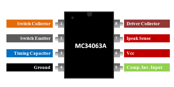
MC34063 Pinout Configuration
|
Pin Number |
Pin Name |
Description |
|
1 |
Switch Collector |
Collector pin of Internal transistors (Output Voltage pin) |
|
2 |
Switch Emitter |
Emitter pin of Internal Transistors |
|
3 |
Timing Capacitor |
Connect to capacitor which decides the switching frequency |
|
4 |
Ground |
Connected to ground |
|
5 |
Comparator Inverting Input |
Used to set the output voltage |
|
6 |
Vcc |
Input voltage is fed to this pin |
|
7 |
Ipeak Sense |
Used to set the output current |
|
8 |
Driver Collector |
Collector pin of switching transistor |
Features
- DC-DC Converter IC (Buck, Boost and Inverter)
- Input Voltage: 3V to 40V
- Adjustable Output Voltage from 1.25V to 40V
- Current Capability: 1.5A (maximum)
- Switching Frequency: 100KHz
- Short Circuit current Limiting
- Driver Collector Current: 100mA
- Precision Internal Reference: 2%
Alternative DC-DC Controllers
UCC25600, LM2596, MCP16252, TC7660
MC34063A Equivalent
ACT4514, CS51411, TS2580
Where to use MC34063A
The MC34063A is a DC-DC converter IC, which is normally used to design Buck (step-down), Boost (Step-UP) or Inverter (DC to AC) circuits. It is an industrial standard IC and can be found in Automobile phone chargers to regulate 5V for mobile phones. Since the regulation occurs through switching it is very efficient than linear circuits.
The input voltage for the IC is from 3V to 40V and the output voltage can be varied from 1.25V to 40V and the maximum output current can be upto 1.5A. So if you looking to design DC-DC converter with above specifications then MC34063A might be of interest to you.
How to use MC34063A
As told earlier the MC34063A can be used to design a Buck, Boost or Inverter circuit. The sample application circuit diagram for all three can be found in the MC34063A datasheet.
The IC requires minimum number of components to be operational. The pin 1 and 2 has a pair of transistors between them which is switching to regulate the required output voltage. The pin 3 is connected to a capacitor which determines the switching frequency of the IC. The output voltage is set by forming a potential divider at pin 5. The formulae to calculate the output voltage can be given by.
Vout = 1.25(1 + R8/R7)
A sample MC34063A circuit diagram for buck and boost circuit using the MC3463A IC is shown below.
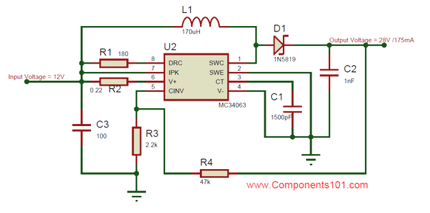
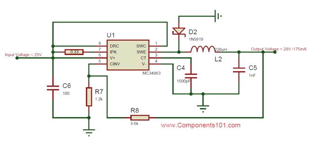
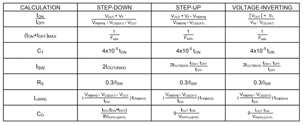
In the above two circuits, the boost converter is designed to convert 12V to 28V with a current rating of 125mA and the buck converter is used to convert 25V to 28V with a current rating of 500mA. There are also options to limit the output current and set the switching frequency using the below formulas in the table, also available on the MC34063A datasheet linked below.
Applications
- Consumer Electronics
- Potable chargers
- Medical equipments
- Battery operated circuits
- Measurement and test devices
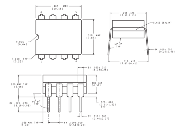
2D Model