MAX1916 - Low Dropout Constant Current LED Driver
The MAX1916 is a highly efficient solution for constant current LED driving. It serves as a high-performance alternative to conventional white LED designs that utilize simple ballast resistors. With the MAX1916, a single resistor is used to set the bias current for three LEDs, ensuring a remarkable matching precision of 0.3%. When enabled, the MAX1916 consumes a mere 40µA of supply current, which decreases to only 0.05µA when disabled. One of the notable advantages it offers over ballast resistors is significantly improved LED-to-LED bias matching. Additionally, it exhibits minimal bias variation even when the supply voltage varies, further enhancing its stability. The MAX1916 boasts a significantly lower dropout voltage and can deliver the desired LED brightness with a dropout voltage of 200mV at a 9mA load on each output. Furthermore, it is known for its potential to significantly improve efficiency in certain applications. The MAX1916 is available in a space-saving 6-pin Thin SOT23 package.
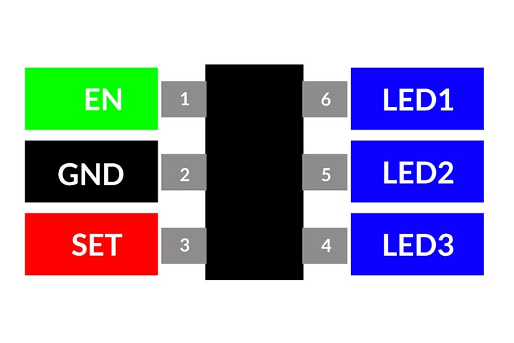
MAX1916 Pinout Configuration
|
Pin Number |
Pin Name |
Description |
|
1 |
EN |
Enable Input/Power Input. Drive high (> 2.5V) to enable; drive low (< 2.2V) to disable. |
|
2 |
GND |
Ground |
|
3 |
SET |
Bias Current Set Input. |
|
4 |
LED3 |
LED 3 Cathode Connection |
|
5 |
LED2 |
LED 2 Cathode Connection |
|
6 |
LED1 |
LED 1 Cathode Connection |
Features
- Low 200mV Dropout at 9mA
- Up to 60mA/LED Bias Current
- 0.3% LED Current Matching
- Simple LED Brightness Control
- Low 40µA Supply Current
- Low 0.05µA Shutdown Current
- 2.5V to 5.5V Supply Voltage Range
- Thermal Shutdown Protection
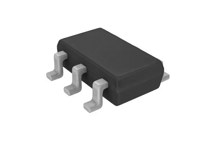
- Tiny 6-Pin Thin SOT23 Package (1mm High)
Alternatives for MAX1916 LED Driver
AL583Q, BP3316D , BD183x7EFV, AN6884, NCP3066
Note: Complete technical details can be found in the MAX1916 datasheet at this page’s end.
Block Diagram

Application Circuit Diagram
The following image shows the typical application circuit for the MAX1916.
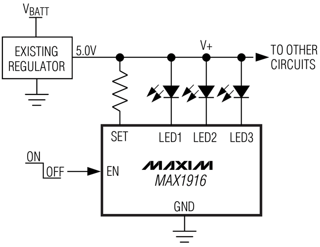
SET pin controls the LED bias current. Current flowing into LED1, LED2, and LED3 is 230 times greater than the current flowing into SET. Set the output current as follows:
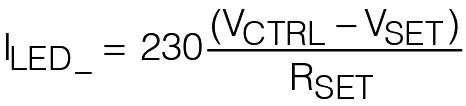
where VSET= 1.215V, VCTRL is an external voltage between 1.8V and 5.5V, and RSET is the resistor connected between VCTRL and SET pin.
Applications
- Digital Cameras and Camcorders
- Next-Generation Wireless handsets
- PDAs, Palmtops, and Handy Terminals
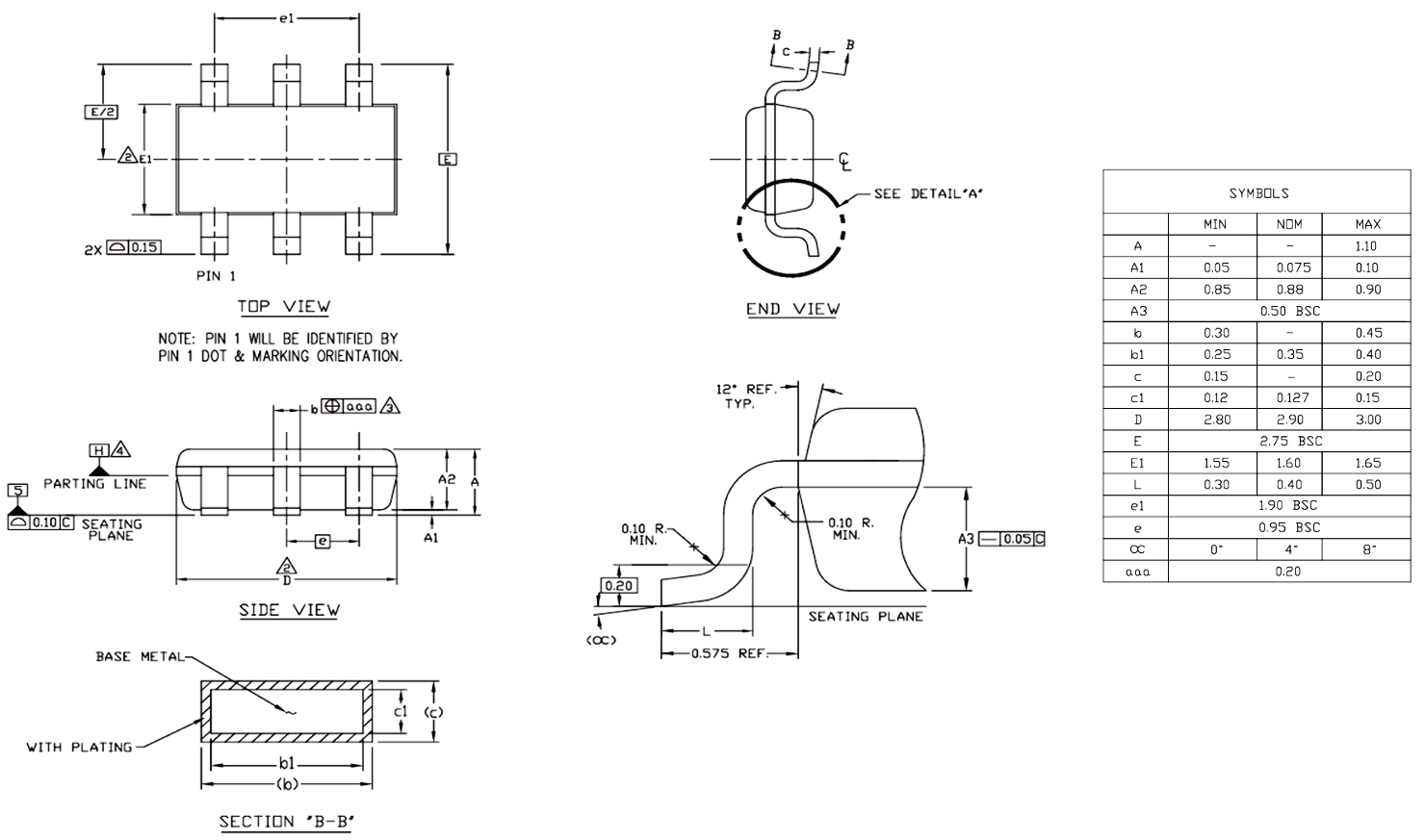
2D-Model and Dimensions
Below is the 2D CAD drawing of MAX1916 motor driver along with its dimensions in millimetres. The dimensions can be used to create custom footprints of the module and be used for PCB or CAD modelling.