LTC4054 - Standalone Linear Li-Ion Battery Charger with Thermal Regulation
The LTC4054 is a constant-current/constant-voltage linear charger for single cell lithium-ion batteries. It features internal MOSFET and doesn't require any sense resistors. It also features thermal regulation during high power operations. The charge voltage is fixed at 4.2V and the charge current can be programmed using external resistor. When the input supply is removed, the LTC4054 automatically enters a low current state, dropping the battery drain current to less than 2µA. The LTC4054 can also be put into shutdown mode, reducing the supply current to 25µA. The LTC4054 also features charge current monitor, undervoltage lockout, automatic recharge, and a status pin to indicate charge termination and the presence of an input voltage.
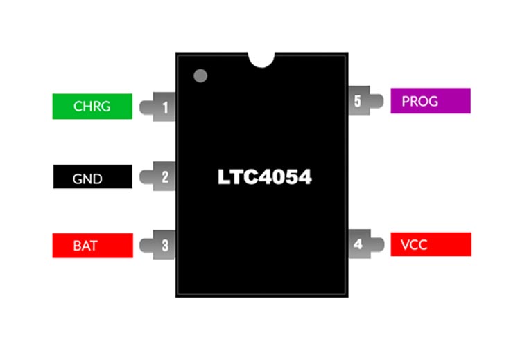
LTC4054 Pinout Configuration
|
Pin |
Name |
Description |
|
1 |
CHRG |
Charge status output |
|
2 |
GND |
Ground |
|
3 |
BAT |
Charger output, connects to battery |
|
4 |
VCC |
Input Supply |
|
5 |
PROG |
Charge current program pin |
Features
- Programmable Charge Current Up to 800mA
- No MOSFET, Sense Resistor or Blocking Diode Required
- Complete Linear Charger in ThinSOT Package for Single Cell Lithium-Ion Batteries
- Constant-Current/Constant-Voltage Operation with Thermal Regulation* to Maximize Charge Rate Without Risk of Overheating
- Charges Single Cell Li-Ion Batteries Directly from USB Port
- Preset 4.2V Charge Voltage with ±1% Accuracy.
- Charge Current Monitor Output for Gas Gauging*
- Automatic Recharge
- Charge Status Output Pin
- C/10 Charge Termination
- Supply Current in Shutdown
- 2.9V Trickle Charge Threshold (LTC4054)
- Available Without Trickle Charge (LTC4054X)
- Soft-Start Limits Inrush Current
- Available in 5-Lead SOT-23 Package
Other Popular Lithium-ion charger ICs
MAX1898 , TP5000, TP5100 module, TP4056, MCP73831, TP4057
Note: Complete technical details can be found in the LTC4054 datasheet at this page’s end.
LTC4054 Application Circuit Diagram
The following image shows the typical application circuit for the LTC4054.
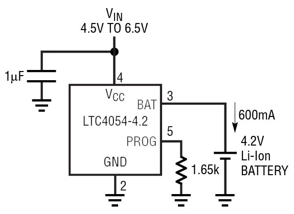
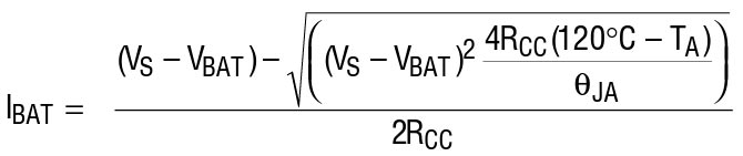
The LTC4054 only requires an input capacitor to maintain stability and improve transient response. The charge current can be set using the external resistor connected to PROG pin. We can use the following equation to calculate the charge current.
Applications
- Cellular Telephones, PDAs, MP3 Players
- Charging Docks and Cradles
- Bluetooth Applications
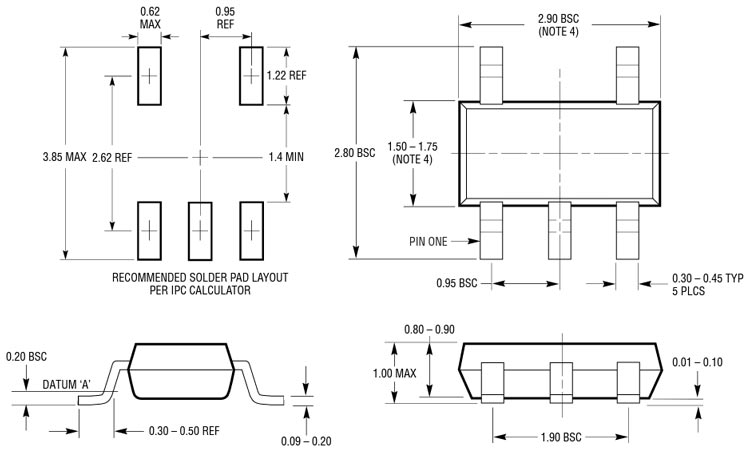
2D-Model and Dimensions
Below is the 2D CAD drawing of LTC4054 IC along with its dimensions in millimetres. The dimensions can be used to create custom footprints of the module and be used for PCB or CAD modelling.