LM431 - Adjustable Precision Zener Shunt Regulator
LM431 is a regulator IC featured with adjustable output voltage. It is a 3-terminal shunt regulator with guaranteed temperature stability over the entire temperature range of operation. The output voltage may be set at any level greater than 2.5V (VREF) up to 36V merely by selecting two external resistors that act as a voltage divided network. Due to the sharp turn-on characteristics this device is an excellent replacement for many zener diode applications.
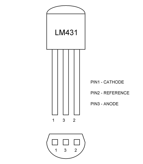
Pin Configuration
LM431 has three pins and function of each pin is mentioned below.
|
Pin |
Name |
Function |
|
1 |
Cathode |
Shunt current/Output voltage |
|
2 |
Reference |
Reference pin for adjustable output voltage |
|
3 |
Anode |
Anode pin is normally grounded |
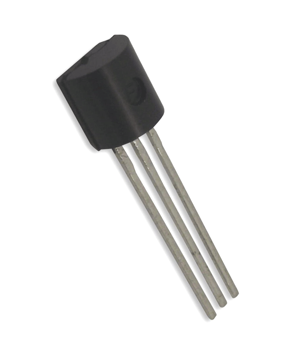
LM431 is available in different packages for different purposes.
Features and Electrical Characteristics
- Programmable output voltage
- Fast turn-ON response
- Low output noise
- Temperature compensated for operation over the full temperature range
- Average temperature coefficient 50 ppm/°C
- Low-dynamic output impedance
- Available in space saving SOIC-8, SOT-23 and TO-92 packages
- Maximum cathode voltage: 37V
- Maximum reference voltage: -0.5V
- Maximum continuous cathode current: 150mA
- Maximum reference input current: 10mA
- Operating temperature range: 0ºC to 70ºC
- Maximum power dissipation: 0.78W
Similar Components
LM432, NJM2820, NJM2821, NJM2822, ZXRE060
Overview LM431 Regulator
LM431 can be configured in many application circuits and a few are stated in the datasheet. It popular application include,
- The device can be used as low power shunt regulator by using just two additional resistors
- The device can be used to deign high power regulator by using additional transistor and resistors
- The device can also be design a constant current source circuit
How to use LM431 Regulator
Before going for application circuit of LM431, let us first understand the internal working of the device and for that consider the functional diagram of the device as shown below.
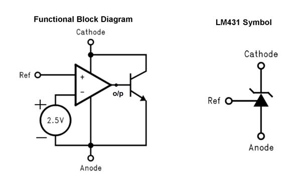
In the LM431 functional diagram we have three main devices namely Op-amp, NPN transistor and +2.5V voltage source. Based on the working of the op-amp, the output voltage Vo/p will be positive only when Vref >+2.5V because voltage at inverting terminal of op-amp is +2.5V.
Now let us consider a simple application circuit for the device as shown below:
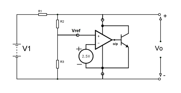
- Here reference voltage (Vref) is the voltage at the non-inverting terminal of the op-amp and this voltage determines whether the op-amp outputs positive voltage or not.
- Also Vref is the voltage at the midpoint voltage divider network formed by the two resistors R2 and R3.
- Based on the concept of voltage division we have Vref = Vo(
- By exchanging terms we have Vo = Vref(
- Based on the equation you can adjust two resistor values in the circuit to get the desired output voltage.
Working of Circuit
The op-amp here keeps comparing voltage at non- inverting terminal which is Vref (which is directly related to output voltage) with +2.5V (the voltage connected to inverting terminal by default) and depending on the result the op-amp triggers the transistor to draw current from the source V1. Whenever the output crosses threshold (threshold is value determined by R2 and R3 value) the op-amp get feedback via Vref and it drives the transistor ON. When the transistor turns ON the device draws current and because of this current drawing a voltage drop appears across R1 resistor which is in series with voltage source V1.
Because of this drop we have Vo = V1 – (R1) * (Ic). Here Ic is the current drawn by the transistor. Also the current draw by op-amp and resistor network is neglected for easy explanation.
The op-amp turns ON transistor up to a point where it’s current drawing leads to lowering Vo (by R1 voltage drop) from V1 to Vref(1+
So in the final result Vo will always be adjusted to float near the measured value by op-amp setup (or LM431). In a similar way we can setup other application circuits.
Applications
- Voltage regulators
- Constant current source circuits
- Zener Diode Replacements
- Voltage Monitoring
- Adjustable Voltage or Current Linear and Switching Power Supplies
- Current Source and Sink Circuits
- Circuits Requiring Precision References
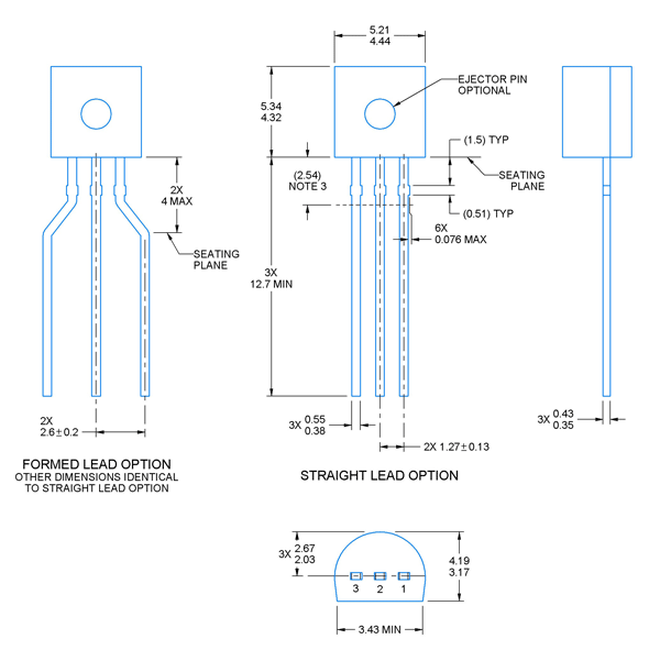
2D-Model
All measurements are in millimeter.