VGA Connector
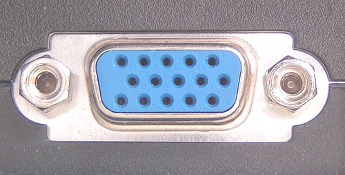
VGA connector is a 3 row, 15 pin connector comes with a screw type locking mechanism.
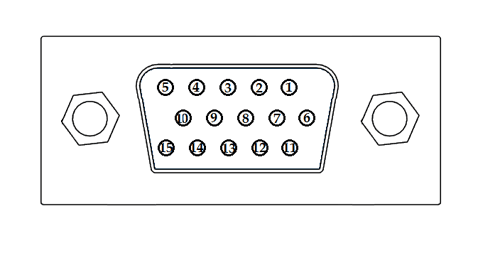
Pinout Configuration
|
Pin No. |
Pin Name |
Description |
|
1 |
RED |
Red video (75 ohm, 0.7V peak-to-peak) |
|
2 |
GREEN |
Green video (75 ohm, 0.7V peak-to-peak) |
|
3 |
BLUE |
Blue video (75 ohm, 0.7V peak-to-peak) |
|
4 |
ID2 / RES |
Monitor ID Bit 2 / Reserved |
|
5 |
GND |
Ground |
|
6 |
RGND |
Red Ground |
|
7 |
GGND |
Green Ground |
|
8 |
BGND |
Blue Ground |
|
9 |
KEY |
+5V DC output from graphic card |
|
10 |
SGND |
Sync Ground |
|
11 |
ID0 / RES |
Monitor ID Bit 0 / Reserved |
|
12 |
ID1 / SDA |
Monitor ID Bit 1 / I2C bi-directional data line |
|
13 |
HSYNC |
Horizontal Sync |
|
14 |
VSYNC |
Vertical Sync |
|
15 |
ID3 / SCL |
Monitor ID Bit 3 / I2C data clock |
Features
- Type – Computer Analog Video Connector
- Data Signal – I2C data channel for DDC information
- Video signal – RGB video signal plus option H and V sync
- No. of Pins – 15
- Connector – DE-15
Brief Description
VGA is a popular display standard, stands for Video Graphics Array. It was first proposed by IBM in 1987. It’s a three row 15 pin connector comes with a screw type locking mechanism. A VGA cable carries analog components RGBHV video signal (Red, Green, Blue, Horizontal sync, Vertical Sync) and DDC data. Due to VGA carries analog signal we may suffer signal loss if we increase the wire length. The maximum resolution that a VGA can provide is 2048 x 1536 pixels. The disadvantage of a VGA is it doesn’t carry audio signal.
Applications
VGA connectors are used to connect the Computer or Laptops (which have VGA connector) to a TV, Monitor or Projector.
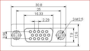
2D-Model