

Capable of supporting up to 32 GT/s without altering design
Understating Bandwidth Limitations in Operational-Amplifiers

Op-amps are the mainstay of analog electronics. You can find them performing a wide range of functions such as amplification, filtering, comparing, and performing mathematical operations among others. However, Op-amps are not infallible – they come with their own set of limitations which must be taken into account when working with them, and the most important parameter is bandwidth.
What Is Bandwidth?
Every circuit has a specific frequency response, which describes how a circuit responds to different frequencies. For example, a simple low pass filter, like its name suggests, allows only low frequencies to pass through. When we feed it an input signal that sweeps from DC to a certain frequency, we get a graph of the ratio of the input to the output (measured in decibels) that looks like this:
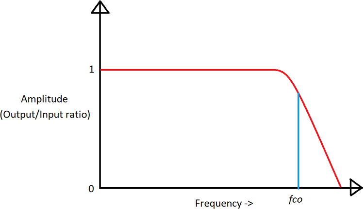
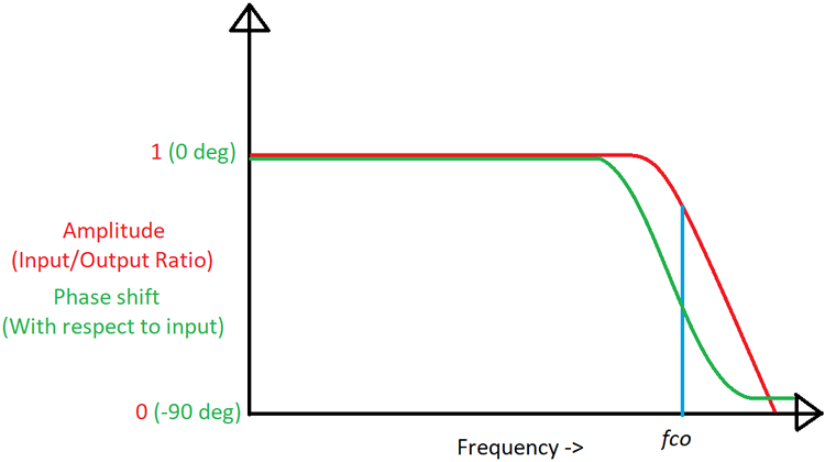
Bandwidth analysis is done in the frequency domain, that is, the x-axis no longer represents time but the frequency. When we plot a graph, the x-axis value represents the input frequency, and the y-axis value is the ratio of output to input. Such a plot is often accompanied by a plot for phase too since there is a delay between the input being applied and the output being interpreted as a change in phase, which makes it useful for mathematical analysis. Such a plot is known as a Bode plot:
What Is Bandwidth in Op-Amps?
Op-amps are just simple amplifiers, so why should they be limited by frequency? It would be surprising to know that op-amps have a built-in feedback network that limits the gain at high frequencies, and for good reason.
Wide-band amplifiers are quite uncommon. More realistically, amplifiers built for specific tasks are usually limited to a specific bandwidth. For example, audio amplifiers are required to amplify only within the human hearing range, which is around 20 Hz to 20 kHz. Amplifying anything beyond this range is a waste of energy and introduces unwanted signals to the audio.
One major thing that amplifiers are prone to be is unwanted oscillations at high frequency. At this point, even small input propagation delays can represent a significant part of the time period of high-frequency signals. If the input-output phase difference equals 180 degrees while the op-amp still has positive gain, then the feedback becomes negative instead of positive and the op-amp oscillates. To avoid this problem, a deliberate gain roll-off is built into amplifiers by adding a feedback capacitor internally.
Important Op-Amp Bandwidth Terminologies
This diagram shows the most important op-amp parameters that deal with op-amp bandwidth:
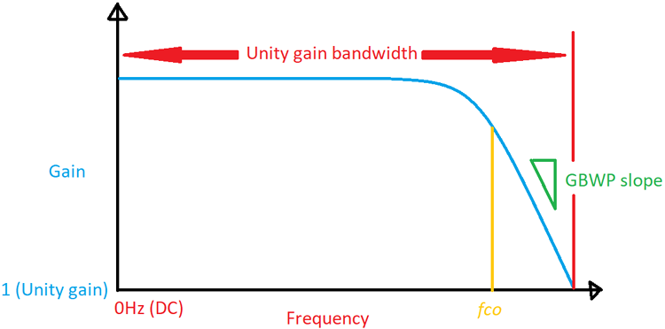
Op-Amp Bandwidth: This specifies the maximum frequency up to which an op-amp can act as an amplifier. All op-amps have internal feedback circuitry that limits the gain at high frequencies to limit unwanted oscillations. The frequency at which the gain of the op-amp begins rolling off depends on the kind of op-amp. At the maximum operating frequency, the gain of the op-amp is exactly one, beyond that, the input signal is attenuated and the op-amp no longer acts as an amplifier.
The fco point is where the gain is 3dB down (-3dB) from the regular gain, in other words, the gain has reduced by 50% at this point. The -3dB point, as this is known, is a common limit used to define the gain limits of amplifiers and filters and is used in formulas for the same.
Gain-Bandwidth Product (GBWP): This is very similar to bandwidth and is the parameter that is most commonly specified in datasheets. As the name suggests, it’s the product of gain and bandwidth and tells us the maximum bandwidth for a given gain.
For example, if an op-amp has a GBWP of 100MHz, then at 100MHz, the gain will be exactly 1. At 50MHz, the gain is 2, and so on. At lower frequencies, this does not really matter, but as the frequency increases, the gain decreases with a slope dictated by the gain-bandwidth product. Gain and bandwidth is a trade-off, for higher bandwidth, you must sacrifice gain and vice-versa. The gain-bandwidth product of an op-amp depends on the value of the compensation capacitor used.
One more point to note is that GBWP is specified for open-loop gain, meaning there are no feedback components to limit gain and bandwidth. The GBWP can change depending on the value and type of feedback. The GBWP is only the upper limit to the performance of an op-amp.
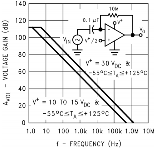
This figure from the LM358 datasheet clearly shows the roll-off mentioned earlier. One interesting thing to note is that at lower voltages, the frequency response is greatly reduced. The LM358 behaves as an amplifier up to a little more than 1MHz.


