Capable of supporting up to 32 GT/s without altering design
Understanding TRIAC Working with Application Circuits

The word TRIAC can be expanded as a TRIode for Alternating Current. While other power electronic switches like MOSFET, IGBT, etc are used for switching/controlling DC power, the TRIAC is used to control AC power because once turned on TRIAC can conduct in both the direction allowing AC voltage to passes completely in both the positive and negative cycle.
The TRIAC is a three-terminal semiconductor switching device that is used for controlling current flow in a circuit. It is one of the most important members of the thyristor family; it is a bidirectional device that can pass the current in both forward and reverse direction, which means that they can conduct in both the conditions of the gate signal, positive and negative.
TRIAC Symbol
A TRIACs can be formed by connecting two equivalent SCRs in inverse parallel to one another and the gates of the two SCR are connected together to form a single gate. If you are new to DIACs as well then you can read the DIAC Introduction Article to know more about it. The Symbol of the TRIAC will be like the image below, it has three terminals Main Terminal 1 (MT1), Main Terminal 2 (MT2) and Gate (G).
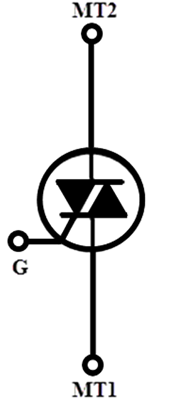
The MT1 and MT 2 are also called as Anode 1 and Anode 2. The TRIAC can be included in a circuit in a way that the current is flowing from either MT1 to MT2 or MT2 to MT1, there will not be any current until we inject a gate current pulse at G.
TRIAC Construction
The below shows the structure of the TRIAC, it is a four-layer device that consists of six doping regions. The gate terminal is designed in a way to have ohmic contact with both N and P regions, which helps the device to get triggered with both positive and negative polarities.
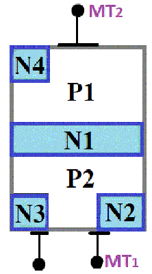
Although TRIAC is a bidirectional device, everyone prefers to specify voltage and current using MT1 as the reference in order to reduce confusion.
TRIAC Working Principle and Operation
TRIAC can go to conduction state if the applied voltage is equal to the breakdown voltage, but the most preferred way of turning on a TRIAC is by providing a gate pulse, either positive or negative. If the gate current is high, a very small amount of voltage is enough to turn on the TRIAC. As the TRIAC is bidirectional and has an ability to get turned on with both the polarities to the gate pulse it can operate in four different types of modes of operation as listed below
1. MT2 is positive with respect to MT1 with a gate polarity positive with respect to MT1.
2. MT2 is positive with respect to MT1 with a gate polarity negative with respect to MT1.
3. MT2 is negative with respect to MT1 with a gate polarity negative with respect to MT1.
4. MT2 is negative with respect to MT1 with a gate polarity positive with respect to MT1.
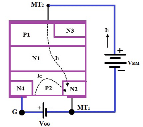
MT2 is positive with respect to MT1 with a gate polarity positive with respect to MT1
When the terminal MT2 is positive with respect to the Terminal MT1 the current will be flowing in the path of P1-N1-P2-N2. During this operation, the junction between the layers P1-N1 and P2-N2 are forward biased whereas the Junction between N1-P2 is reverse biased. When the positive signal is applied to the gate the junction between P2-N2 is forward biased and breakdown occurs.
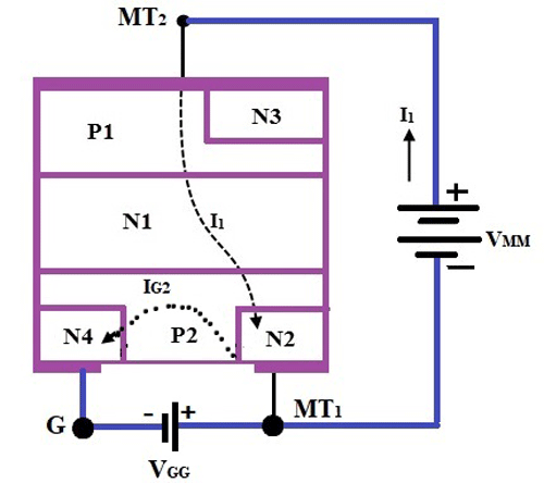
MT2 is positive with respect to MT1 with a gate polarity negative with respect to MT1
When the MT2 is positive and the gate pulse is negative, the current flow will be in the same path as the first mode which is P1-N1-P2-N2, but here the junction between the P2-N2 is forward biased and the current carriers are injected into the P2 layer.
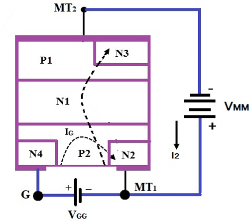
MT2 is negative with respect to MT1 with a gate polarity negative with respect to MT1
When the terminal MT2 is positive and negative pulse is provided to the gate terminal the current will be flowing in the path of P2-N1-P2-N2. During the operation the junction between the layers P2-N1 and P1-N4 are forward biased whereas the junction between the layers N1-P1 is reverse biased, hence the TRIAC is said to operate in the negatively biased region.
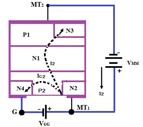
MT2 is negative with respect to MT1 with a gate polarity positive with respect to MT1
When the terminal MT2 is negative and the gate is triggered with a positive pulse the junction between P2-N2 is forward biased and the current carriers are injected, hence the TRIAC is turned on.
The TRIAC doesn’t usually operate in mode 4 because it carries a disadvantage that it should not be used for circuits with high di/dt. The sensitivity of triggering of TRIAC with mode 2 and 3 is high and negative gate pulse is used in case of a marginal triggering capability. The triggering of mode 1 is even more sensitive than mode 2 and 3 triggering but it requires a positive gate pulse for triggering. In most of the cases, the triggering mode 2 and 3 are preferred.
VI characteristics of TRIAC
Since the TRIAC is a bidirectional device it’s the VI characteristics curve of TRIAC will be on the first and third quadrant of the graph, which is similar to the VI characteristics of a Thyristor. If you are completely news to Thyristors like SCR you can check the Introduction to SCR article. When the terminal MT2 is set to be positive with respect to the terminal MT1 the TRIAC will be operating in the forward blocking mode.
During the initial stage due to the resistance of the TRIAC, there will be a small leakage current flowing through the device as the applied voltage is less than the breakdown voltage. When the voltage is increased and it reaches the breakdown voltage the TRIAC is turned on and high current starts flowing through the device.
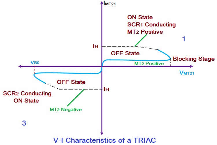
Apart from increasing the voltage of the device the TRIAC can be turned ON by applying the gate pulse, even if the applied voltage is less than the breakdown voltage. The same operation can be carried out in the negative direction of the TRIAC which can leave us with a mirror image of the same curve on the negative quadrant. The supply voltage at which the TRIAC starts conduction will depend on the gate current applied to the TRIAC. If the gate current is higher, then the voltage required to turn ON the TRIAC can be less. The characteristic curve that is given above shows the operation of TRIAC in mode 1 on the first quadrant and mode 3 on the third quadrant.
TRIAC Application:
As mentioned earlier, TRIACs are commonly used to switch AC voltages. A sample application TRIAC circuit for AC switching is shown below.
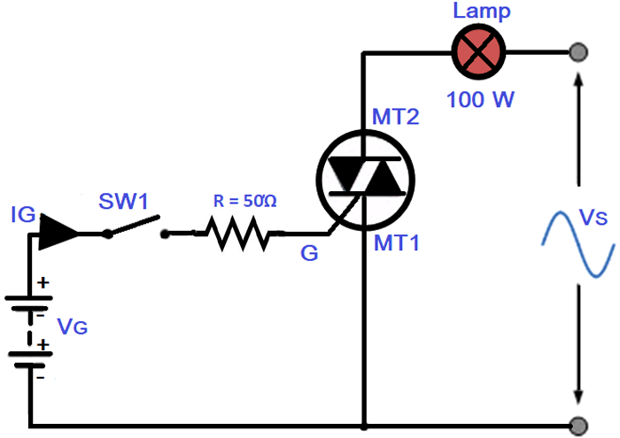
The above circuit shows the typical set up of a switching system using a TRIAC. Initially, when the switch SW1 is open there will not be any supply to the gate circuit and the current flow will be zero through the lamp. If the switch is turned ON the current starts flowing through the resistor R and there will be a pulse provided to the Gate terminal G. The given gate pulse will help in breaking down the junctions of the TRIAC and help it conduct, hence the AC voltage Vs will be allowed to flow through the circuit and lights up the Lamp.
TRIACs can be used in various applications such as
- Control circuits like electric fan speed control and smaller motor controls
- High Power lamp switching and light dimmers
- AC power control domestic appliances
Different types of TRIAC Packages
For the Convenience of usage and different applications, the TRIACs are designed in different packages like pin/standard type, Capsule/Disc Type and Stud Type.
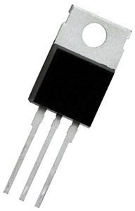
Pin/standard Type: The Standard Type TRIACs will be looking like a small IC with three Pins which are the MT1, MT2 and gate (G) and a heat sink on the top. These types of TRIACS are used in Domestic electronic appliances. Some of the common packages are TMA36S-L, TMA54S-L, TMA84S-L, TMA124S-L, TMA126S-L, TMA206S-L, TMA106S-L, etc.

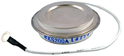
Capsule/Disc Type: The Capsule/Disc Type TRIACs will be in the shape of the disc with extended wires to the terminals. These TRIACs have a high current capability and are made with a ceramic seal. They can be used in applications such as fast motor control and AC switching. Some of the common packages of Disc type TRIACs available in the market are KS100A, KS200A, KS300A, KS500A, KS600A. KS800A, KS1000A.
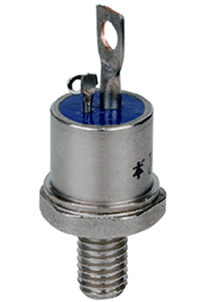
Stud Type: The stud type TRIACs are mostly used in high power applications, they have a screwed bottom that acts as one of the main terminals, and has two terminals on its top which are the other main terminal and the gate. These TRIACs can be used in phase control applications in a converter, lighting circuits, Regulated power supplies, and temperature and speed control circuits and power supply an motor control. Some of the common packages available in the market are TO-118, TO-93, TO-48, TO-94, TO-48, TO-65 and RSD7