

Capable of supporting up to 32 GT/s without altering design
Relays and Contactors: Types, Working and Difference between them

Relays are basically switches which are primarily used for the protection of equipment. It generally uses two circuits – A control circuit and a power circuit. The control circuit regulates the flow of power and performs the basic switching operation using a small amount of current which can in turn be used to control a circuit with a high amount of current. In small scale applications, fuses and similar devices are used for protection purposes. In large scale industries, where high reliability is required, relays are preferred.
Types of Relay
Relays are broadly classified into three categories depending upon their construction and working.
- Electromagnetic relays
- Static relays
- Digital / Numerical relays
They can also be classified as:
- Time delay relays
- Protective Relays
- Solid State Relays
We will discuss all of them in detail below.
Electromagnetic Relays
The working principle of electromagnetic relays is the electromagnetic action. The fundamental construction aspects of an electromagnetic relay are very simple. It consists of three parts –
- Electromagnet
- Movable armature
- Contacts (NO and NC)
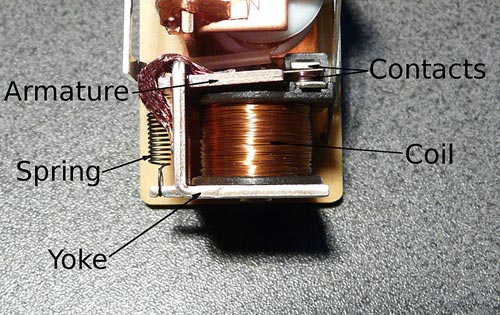
Electromagnet – This is a temporary magnet that becomes a magnet only when an electric current is passed through it. An electromagnet is formed by wounding a wire around a soft iron core. Whenever electric current is passed through the wire, a magnetic flux is induced in the iron core which makes it act like a magnet and produce a magnetic field around it.
Movable Armature – This is commonly known as a plunger or a solenoid. It is the movement of this part that opens or closes the mechanical contacts as it is attracted by the magnetic field generated by the coil.
Contacts (NO and NC) – There is one stationary contact and one movable contact. The movable contact moves in response to the magnetic field generated by the electromagnet, thereby making the contact Normally Close (NC). The contact breaks open in case there is any fault detected in the system.
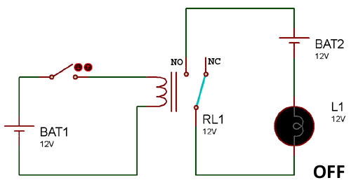
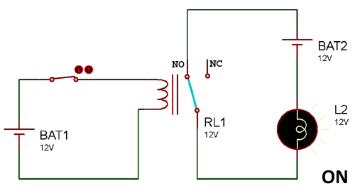
The figures illustrate the working of an electromechanical relay. The relay is energised by the magnetic field generated due to the electromagnet and thereby changes its contact from Normally Open to Normally close. Only when the relay contacts are Normally close, the power circuit is completed and the load (bulb in this case) gets the power. In case of any fault, the contact changes to Normally Open, thereby causing an interruption in the flow of current and ensuring the safety of the equipment.
Electromagnetic relays can be further classified as-
- Electromagnetic attraction
- Electromagnetic induction
Static Relays
Static relays are those relays which do not contain any moving parts. They are contrasted with electromechanical relay, which has moving parts for switching. Static relays incorporate static components such as solid state devices, magnetic or electric circuits etc. to obtain output instead of mechanical contacts. Static relays utilize high reliability operational amplifiers (Op-Amp) for the realisation of its basic components.
The basic circuits employed in Static relays are –
- Comparators - Phase comparators
Amplitude comparators
- Timers
- Level detectors
- Integrators
- Polarity detectors
Due to the absence of moving parts, static relays offer many advantages over the conventional electromagnetic relays. Some of them are –
- Fast operation and hence fast clearance of faults,
- High resistance to vibrations and shock,
- Quick reset action,
- Low maintenance etc.
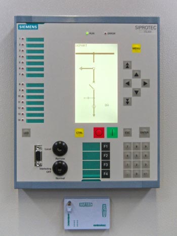
Digital or Numerical Relays
These relays are usually microprocessor based and are programmable according to the needs of the user. They are more user friendly and offer multi-functional protection schemes. Unlike electromagnetic relays, these do not contain any moving parts and thereby serving all the benefits of static relays as well. Due to these factors, numerical relays are referred to as present generation relays. One of the major advantages of numerical relays is that it can store pre-fault as well as post-fault data so that it can be used further.
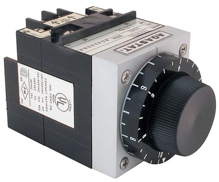
Time Delay Relays
Time delay is type of electromechanical relay which are used to provide a delay in the start-up, shut-down or controlling processes. These relays induce a time delay in making its contact Normally close after the coil has been energized. This is done in order to meet the desired requirements. These are broadly classified into two types, namely – ON delay time relays and OFF delay time relays.
ON delay time relays
In this type of relays, the timer starts during start-up i.e. when the voltage is applied and the coil is energised. Once the timer reaches the set timing, it stops and the contact closes thereby completing the circuit and turning on the equipment. The ON delay time relays involve two types of contacts –
Normally Open – Timed Closed
Normally Closed – Timed Open
- Normally Open – Timed Closed – This contact remains normally open as long as the coil is de-energized. Once the coil is energized, the timer starts and works till the set time. When the timer reaches the set time, it stops and the contact becomes closed, thereby turning On the equipment connected.
- Normally Closed – Timed Open – This contact is normally closed before the power signal is applied i.e. the coil is de-energized. As soon as the power signal is applied and the specified amount of time has been recorded, the contact opens.
OFF delay time relays
In these types of relays, a delay is introduced during shut down of the equipment. The off delay timer starts only when the power is removed from the circuit i.e. no power is being given to the circuit anymore and the coil is de-energised. The two types of contacts involved in OFF delay time relays are –
Normally Open – Timed Open
Normally Closed – Timed Closed
- Normally Open – Timed Open – This contact remains normally open when the coil is de-energised and closes as soon as power is applied to the circuit. The timer starts during de-energisation of the coil and makes the contact open as it reached the specified time.
- Normally Closed – Timed Closed – When there is no power applied to the coil, this contact is normally close and open when power is given to the circuit. Here also the timer works during de-energisation of the coil.
Protective Relays
A protective relay is a device that is used to trip the circuit breaker during fault or abnormal conditions. It senses the fault and gives the command to trip the circuit breaker to isolate the faulty element so as to prevent any further damage.
The supply to the system continues and as soon as the fault is cleared, the system works in its normal state again. The relay should be able to differentiate between transients and faults so that it trips the circuit breaker during faults only and not during transients.
There are two types of protective relays namely primary relays and back-up relays. The primary relay acts as the first line of defense and if it fails to operate due to any reasons, then back-up relays are put to operation. Depending upon the actuating quantity, these relays are classified as the following:
- Over-current relay
- Directional relay
- Distance relay
- Differential relay
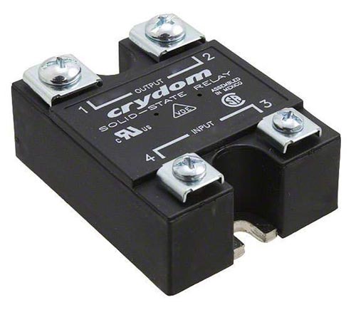
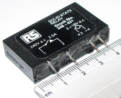
Solid State Relays
Solid state relay may fall under Static Relays. It is a electronic switching device built to overcome the disadvantages of traditional relays such as slow switching action, reliability etc. Solid State relays make use of optical and electrical properties of semi-conductors and does not employ any moving parts. An opto-electronic isolator or opto-coupler is present between input and output circuits.
Working of a Solid State Relay
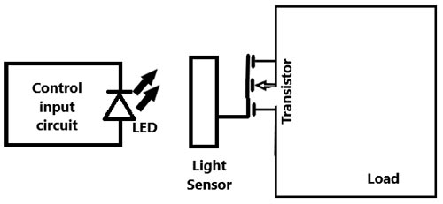
The Solid State Relay consists of an LED, a light sensor and a transistor apart from the input and output circuits. Whenever a control input is given, i.e. power is applied to the input circuit, the LED glows thereby emitting light. The light sensor then detects the glow and closes the connected transistor. After the transistor is closed, current flows through the load circuit. As long as the transistor remains open, there is no flow of current through the load circuit.
As there are no moving parts, the switching action is fast and reliable and less amount of wear and tear is caused to the equipment. It also eliminates sparking, corrosion and vibration issues.
Contactor
A contactor is basically an electrical switch which makes or breaks the contacts just like a conventional switch. It differs from the conventional switch due to an electromagnet which it incorporates in order to hold the contacts. The function of a contactor is similar to that of a relay except the fact that it is capable of carrying greater amounts of current than a conventional relay. Also, unlike relay contactors cannot provide protection. They are only used in making or breaking the contacts. Contactors find their application in high current circuits, usually those with a rating higher than 20 Amperes.
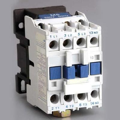
Construction of Contactor
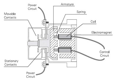
A contactor consists of the following components –
- Contacts (Movable as well as stationary)
- Electromagnet
- Armature
- Spring
- Power circuit and Control circuit
- Coil (AC and DC)
The contacts are of two types namely the power contacts and the auxiliary contacts and they are connected to the springs. The contacts along with the electromagnet are enclosed in a frame made up of insulating materials. Insulated materials are used so as to prevent the touching of the contacts.
An additional supply is given to the electromagnet for its excitation. Sometimes the electromagnet is split into one fixed half and another movable half with a spring in between to hold them apart. The movable half is connected to the movable contact.
If the contactor has a DC coil, solid steel or soft iron is used to make the electromagnetic core whereas if the contactor has an AC coil, laminated soft iron is used to make the electromagnetic core so as to reduce the amount of eddy currents.
Operation and Working of Contactors
Contactors are generally used for high currents. Whenever the electromagnetic coil present in the contactor is energized, it produces an electromagnetic field. The armature which is a metallic rod is then attracted by the produced electromagnetic field. If the electromagnet is split, then the movable part is attracted towards the fixed part. And hence the contacts are closed are remain in the same position as long as the electromagnet is excited. Now when the de-energization of the coil occurs, the moving contact moves back to its initial position through the spring. This contact making and breaking action occur very rapidly. Contactors consume a very small amount of power during its operation which can be further reduced by using economizer circuits.
Relay vs Contactor
Relays and contactors both perform the switching operation. Both of them can be differentiated on the following bases:
- Size – Relays are relatively smaller in size than contactors.
- Load Capacity – Relays carry currents of capacity less than 20 A while contactors are designed to carry currents of much higher capacity (generally greater than 20 A and up to 12500A).
- Contacts – Relays can operate on either Normally Open or Normally Close contacts depending upon the requirement whereas contactors are designed to operate usually with Normally Open contacts. The contacts in contactors are often connected to a spring to aid better and reliable switching with more safety
- Arc Suspension – Relays operate at lesser voltages and are therefore not concerned with arc whereas on the other hand, contactors show the phenomena of arc suspension so as to prevent damage to the equipment. Therefore, an arc chute is present in contactors and is absent in relays.


