Capable of supporting up to 32 GT/s without altering design
How to Check for Saturation Current, Core Loss, and other Parameters to select an Ideal Inductor for your Design

Inductors are widely used passive components in electronics, mainly in the area of Analog and Power supply Design. Even though, the construction of an Inductor appears very simple, like just a copper wire is wound in a particular shape with or without a core, it has a very large working principle as well as different parameters for different applications.
It is widely used in power electronics, audio electronics as well as in analog RF communication network circuits. Since each application is different, inductors can have different shapes and sizes, different construction, and obviously the properties of an inductor that is suitable for one application will be very different from the one used in other applications. In the previous, we have already discussed the basics of Inductor and the different types of Inductors with the application. In this article, we will get introduced with different parameters of inductors and check how to select one that matches your specification requirement.
Parameters of Inductors
Different types of inductors pose different specifications in different parameters. Due to the difference in inductor parameters, specific applications require special types of inductors. Therefore, It is essential to know what are the different types of parameters processed by an inductor.
Any Inductor will have the following parameters-
- Inductance.
- Coil DC resistance or DCR.
- Rated current.
- Core construction and permeability.
- Self-Resonant frequency.
Inductance
The first and most important parameter of an inductor is its inductance. The inductance of an inductor determines how much current it will oppose through the inductor. Therefore, where a larger value of inductance is required, a smaller value of inductor will not work and vice versa.
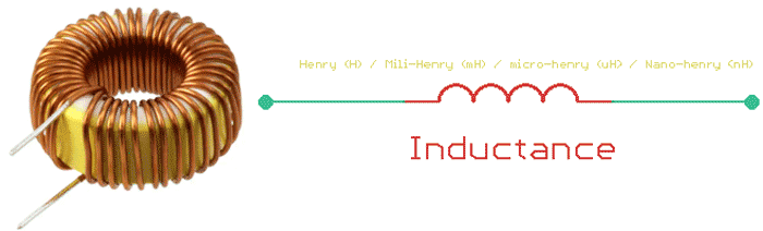
The SI unit of inductance is Henry. 1 Henry of inductance will oppose 1 ampere of current changes and produce 1 volt of electromotive force. In electronics, 1 Henry of inductance is very rare since it is a very large value to be applicable in most of the circuits, specifically in power electronics, the largest value of an inductor will be in Milli-Henry (mH) (in different types of transformers). Most of the time, inductance with micro-Henry (uH) rating will be applicable in different types of power applications or switching circuits.
Moving on to the audio electronics such as filters or in radio frequency applications, the value of inductance can be used as low as in nano-henry (nH) to a maximum of micro-henry. In some specific cases, an audio Transformer or inductor uses the inductance of MilliHenry to henry rating. Inductance can be measured using an LCR meter.
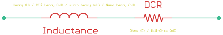
DC Coil Resistance (DCR)
Inductors oppose the current in varying signals, it acts as a direct path for DC operations. In DC operations, the inductor poses resistance that will dissipate heat as per the ohm's law. DC resistance of an inductor is an important parameter since it will affect the overall performance of an inductor. An ideal inductor will not have any kind of DC resistance but in case of real inductors, even if the inductor is constructed using a thick copper wire, it will still have some amount of DC resistance. This resistance value of the Inductor is called Inductor DCR. In specific applications where low DCR value is expected, high DCR value will decrease the overall efficiency of the circuit.
The DC resistance of an inductor is measured in ohms and considered for a steady current that is normally flowing through the inductor. For those who want to measure the DCR value of an inductor, can use the ohm's law as V = I x R.
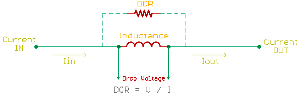
Since DCR is considered for a steady-state current through the inductor, an inductor can be used as a series conductor in a close path and DC current is needed to be flown through it. As the inductor acts as a series resistor (DCR), as per the ohm's law, it will produce a voltage drop across it. By sensing the voltage and knowing the value of the current flow, one can determine the DCR value of an inductor.
Inductor Current
An inductor is specified for three types of current that is essential for any kind of application. Those are rated current, saturation current, and incremental current.
All inductors are specified for a maximum continuous current that an inductor can withstand. This is called the rated current of an inductor. This rated current is limited by the factor of temperature rise of an inductor during constant operation in a circuit. Continuous current flow through an inductor that is more than the rated current of the inductor, will induce temperature rises that will cause lower reliability, burned inductor, or failure and will dramatically affect the overall efficiency of the circuit. It is important to consider the rated current of an inductor, before choosing one.
Inductors work with magnetic flux and it is highly dependable on the saturated current of an inductor. Exceeding saturation current of an inductor will cause saturation in the inductor core which resulted in a fall of actual inductance value, thus not meeting the circuit requirement. Saturation current is an important parameter for those inductors that are used in power electronics-related applications.
Core Construction and Permeability
The permeability of an inductor core is another key parameter since inductance size, shape, and geometry are essential for different applications.
For example, the switch mode power supply design requires a small size of Transformers and inductors to reduce the overall size of the circuit. Also, high inductance can be very useful for high-frequency switching operations. But using only copper wires, it is impossible to get high inductance in low size and shape. Thus, the core construction of an inductor is essential. High permeability core material increases the inductance by maximizing the flux density in small shape and size.
However, irrespective of the core materials, an inductor will dissipate heat across its winding and core. The power dissipation across the core area is referred to as the core loss of an inductor. The core loss of an inductor is often given by the inductor suppliers. If the core loss is not available in the inductor datasheet, it can be easily calculated by the below formula -
Pcore (mW) = K1fxBy × V
Where,
K1 = Constant for core material
f = Frequency in kHz
B = Peak Flux Density in kGauss
x = Frequency exponent
y = Flux Density exponent
Ve = Effective core volume (cm3)
Self-Resonant Frequency
An inductor has winding capacitance or self-capacitance that affects the switching frequency of the inductor. Due to the construction of inductors, in between the windings, a self-capacitance is formed, that acts as a parallel resonant circuit.
Not only for power electronics, but self-resonant frequency consideration is also important for radio frequency, audio applications where the inductor is used in filter design. Generally, inductor self-resonant frequency is the point where the inductive reactance and capacitive reactance will cancel each other and the overall impedance of the circuit will only be controlled by the DC resistance of the Inductor.
Due to this, an inductor is used below their self-resonant frequency for reliable operation and the self-resonant are not experienced. Therefore, one should select an inductor where the self-resonant frequency of the inductor is much higher than the switching frequency of the circuit.
Q-Factor
Since any metal conductor has inductance (maybe in small amounts of inductance), it varies a lot depending on the metal type. For the selection of the metal, the Q factor is taken into consideration. The Q factor is the ratio of inductive reactance to its resistance at a given frequency. A Higher Q factor means closer behaviour to an ideal inductor. In most of the cases, inductors are solely made using copper wires due to this high Q factor.
How to Select an Inductor for an Application
Since an inductor poses different types of parameters that are suitable for a specific type of application, it is important to select an inductor based on the type of application it is required for.
Step 1: Select an inductor is to know the type of application. For a power electronics related application, multiple types of inductors can be required such as Transformers, chokes, EMI filters, etc. Choose the specific type of inductors based on the requirement.
Step 2: Know the required inductance for the circuit. In the case of audio electronics where filter design is required, the exact value of inductance is a must that will ensure proper signal filtering. Close to a 1% tolerance inductor value is a good choice.
But for the case of power electronics, the inductance versus size is also an important consideration because the inductance for a specific size is related to the type of core it uses. For small size and high inductance, one can use ferrite core inductors and Transformers that can be really helpful for high-frequency switching operations. Choose the exact inductance value of inductors in case of EMI filters, Chokes, and LC circuits.
Step 3: Know the rated current of the inductor. For a switching converter, where 2 amperes of current will flow through the inductor, it is important to choose an inductor with a rated current that is more than the required current. How much current rating is actually required is dependent on the type of switching topology used. It is better to refer to the datasheet of the switching driver. But generally, an inductor with more than one-third of the required current is a good choice for both CCM (Continuous Conduction Mode) or DCM (Discontinuous conduction modes) switching topology.
Step 4: Choose an inductor that matches the switching frequency. For the switching circuits, inductor manufacturers provide inductors for a specific switching frequency. It is important to match the switching frequency of the inductor with the switching frequency of the circuit to eliminate the self-resonant effect. The core type of an inductor also affects the switching frequency of the inductor. For example, Ferrite core generally uses Khz to Mhz switching frequency.
Practical Example
Let's consider the below circuit. Which is a switching boost regulator using the driver MIC2253. The output is 5.0V and is capable of providing 3.5A from a 1 or 2 cell lithium-ion battery.
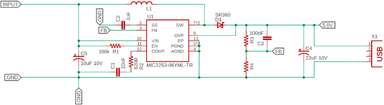
Now to select the inductor L1, the following information should be considered-
- The driver provides a maximum of 3.5A of current.
- The driver works at a fixed frequency of 1 Mhz.
- Small size preferred due to the application size of this circuit will be small.
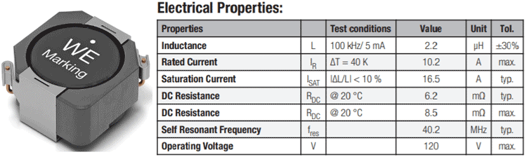
To select the component the datasheet showed that it uses a fixed 2.2uH of an inductor. But the current value is not given. Therefore, since the maximum output of the circuit is 3.5A, an inductor with more than 3.5A current rating is required. Also, since the frequency 1 Mhz, an inductor with more than 1 Mhz self-resonant frequency is required. The DCR will be expected as low as possible due to the increased scope of minimum power dissipation even in such 3.5A current flow. So, the inductor should have the following specs-
- > 3.5A continuous current rating
- > 1 Mhz Self Resonant frequency
- Very low DCR expected in mili-ohms rating
- 2.2uH inductance is required
Any inductor that has the following specs can be used. However, one example is the 7447706022 inductor for Wurth Electronics, shown below. It is a small size inductor and meets the minimum requirements of the circuit.