

Capable of supporting up to 32 GT/s without altering design
How does Digital Potentiometers work, why and where should you use them?

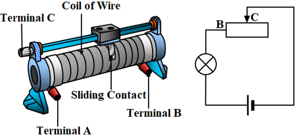
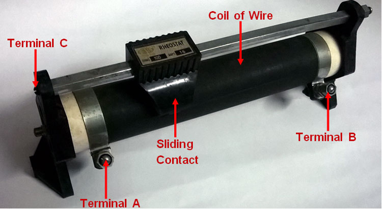
A potentiometer is a variable resistor that can be used in a circuit to control resistance, current, and voltage through a circuit to attain a certain output, we already know the basics of Resistor and how they work. The potentiometer is just a variable resistor, sometimes also called a rheostat, which you all could have seen in your physics laboratory, it consists of a metal coil wound on a cylindrical platform that consists of a sliding contact that is used to control the resistance of a circuit. A typical Rheostat is shown in the picture below
The potentiometer (POT) has a similar function, but in a constrained space and has a different design like the typical Radio Potentiometers, Preset Potentiometer, Thumbwheel Potentiometer, etc. You could have used potentiometers in many places unknowingly, for example, the volume controllers in your stereo are potentiometers and the regulators that are used for controlling the speed of ceiling fan is also a form of the potentiometer. Similarly, everything that controls the output of a system by varying the resistance, current, and voltage is a form of the potentiometer. All this is being said just to make you understand how important potentiometers are, now what if you want to automatically control the volume or tune your radio without actually turning the knob? This is where the digital potentiometer comes in. In this article, we will learn more about digital potentiometers, how they work, and how you can use them.
What is Digital Potentiometer?
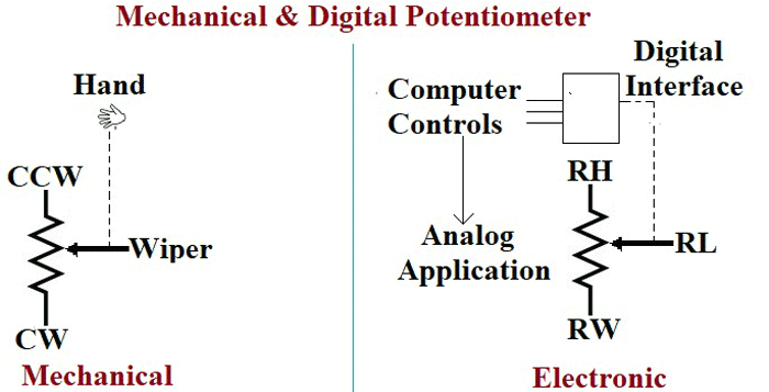
The mechanical potentiometers are used for manual controls where someone should physically vary the resistance of the device to change the output. But a digital potentiometer can automatically vary its resistance depending on the given condition. A digital pot acts exactly like a potentiometer whose resistance can be varied by digital communication (like I2C, SPI) instead of rotating the knob directly.
The mechanical potentiometers are called the POT because of its pot like structure which consists of three terminals for input, output, and ground along with a controller on its top that is used to control the resistance by turning it in clockwise or anticlockwise.
The biggest drawback of the POTs is that they are easily affected by environmental factors like dust, dirt, and moisture that could seal the wiper shaft, this made them unfit for certain kinds of applications. To overcome these drawbacks Digital Potentiometers or shortly digiPOT was introduced, the digiPOTs can work in environments with vibration and particles like dirt, dust, moisture, and grease without changing its nature of the operation.
Why digiPOTs are preferred over the POTs?
DigiPOTs are better protected in various environmental conditions as they are encapsulated in the form of an IC. They are less vulnerable to vibrations and they can’t tamper physically, this makes them more reliable to use. The digiPOT can fit in a tiny IC package of 2.9mm x2.8mm or even smaller space which can be easily mounted on a PCB board. The most popularly used MCP41010 Digital Potentiometer IC is sown below
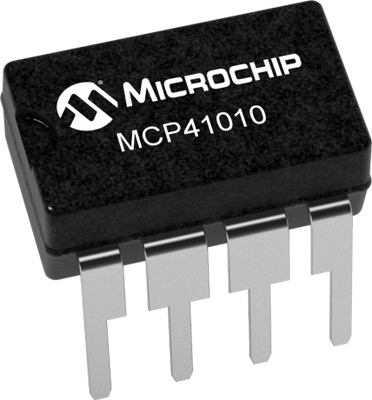
The MCP41010 includes a quad pack of digiPOT in a single package along with shutdown mode and programmable pre-set positions upon power on the wiper position. They offer higher resolution, greater stability and solid-state reliability for all kinds of applications.
Working of Digital Potentiometer
To understand how a digital potentiometer works, let's look into the Architecture of a digital potentiometer. It is really simple as it has only one function to perform in a circuit, to control the current/voltage based on the given condition. The blocks of an electronic potentiometer include a Series of resistors, a Memory unit, and a Control / Interface unit
Series of Resistors
The Digipots are built by connecting a series of resistors in a ladder-like structure; each step of the ladder consists of a switch that is connected to the output of the potentiometer. The resistance of the device is determined by calculating the number of steps it has, the higher the number of steps greater is the resistance value.
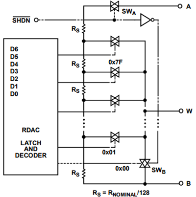
So, in order to determine the number of steps you need to use the bit value that is if the digipot has N number of bits, it means it has 2N steps. For example, if the number of bits is 6 then 26 = 64 steps, If the number of bits is 9 then 29= 512 steps.
Memory Unit
All the digital devices have some sort of memory for their operations, as the digital potentiometer is also a form of digital device they also have a memory unit. They mostly have a volatile memory unit, the volatile memory units are used only during the operation and they will not store any prior information once they are shut down. Hence, most of the digipots start from the first step while they are restarting, in some cases these devices are interfaced with FPGA or the micro-controller to store the last position.
There are some special digipots available in the market that make use of Non Volatile memory where the last step of the potentiometer is stored within the device so that the last step of the device will be retained even after shutting down the device.
Control and Interface unit
The control unit is the most important unit of a digital potentiometer, as it is the unit that differs the digital potentiometer from the traditional potentiometer. The control unit is where the control signal is sent from a microcontroller like Arduino to vary the resistance of the digital potentiometer.
Almost all the potentiometers have a synchronous or an asynchronous series bus as an interface in the control unit, apart from that some digital potentiometers use control logic or front panel switches. The increment/ decrement interface bus is the most common asynchronous bus used in the digital potentiometer that makes use of a UP/Down Counter. The blew block diagram shows a digital potentiometer with an increment/ decrement control interface.
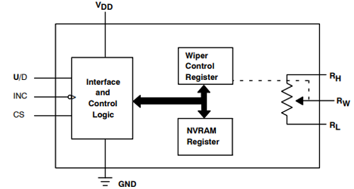
The increment /decrement interface uses three signals as you can see from the image above, the signals are
CS: CS is the Chip Select (CS) signal, it is used as an address input for multiple digital pot applications when it is enabled.
U/D: The wiper of the pot should be moved up or down to increase or decrease the resistance of the potentiometer. This process is enabled by the Up/down (U/D) signal.
INC: The increment (INC) signal also used to move the wiper, the wiper moves at every falling edge of the increment signal.
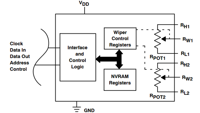
As I said the Increment/Decrement interface is the most commonly used asynchronous bus, similarly the most used synchronous buses are SPI, I2C, two-wire, and microwire-like buses. Out of these buses, I2C & SPI are the most preferred type of interfaces. The below blog diagram shows a digital potentiometer with an I2C Control interface.
The I2C bus has two main signals, namely
SCL/SCK: It is the serial clock of the interface that synchronizes the control section.
SDA: SDA can be expanded as serial data, the serial data lines are used to transfer the data from the interface to the control. The SDAs are bidirectional in nature, hence they can communicate in both the directions.
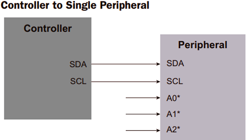
Similarly the SPI Control interface Digital Potentiometers have four main signals as shown below. Again the Controller can be any microcontroller like Arduino, PIC, AVR or Raspberry PI and the Peripheral can be any digital potentiometer
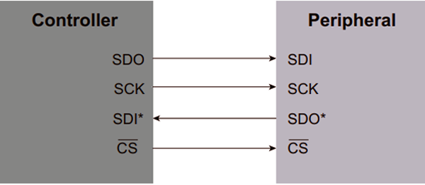
CS: The Chip Select (CS) /Slave Select (SS) is used to select the required control system if more than one control system is connected to the interface.
SCK: SCK is the serial clock of the interface.
SDI: SDI stands for Slave Digital Input, here the slave can be the control system, and hence the input from the control system is delivered as the SI signal.
SDO: SDO stands for Slave Digital Output, Similar to Slave Input the SO is the output signal to the control system from the interface.
How to choose a digital potentiometer for an application?
If you want to choose the right digital potentiometer for your applications you should consider the following parameters
Resistor Configuration
You must choose how your digital potentiometer should operate, as the digital potentiometer can operate in two different configurations, one as a potentiometer or as a rheostat.
In Potentiometer mode, the configuration consists of three terminals A, B and W, here the digital potentiometer operates as voltage driver. The wiper’s terminal voltage is directly proportional to the voltage applied between the terminals A & B and the resistance at RAW & RWB. The potentiometer configuration is mostly preferred for applications such as DAC, LCD VCOM Adjustment and analog signal attenuation.
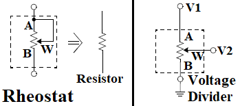
In Rheostat Mode, the digital potentiometer will operate as a digitally controlled rheostat in which only two terminals are considered, the unused terminal can be left unused or can be tied to the W terminal. The end to end resistance of the device has 2N contact points accessible by the wiper terminals. The resulting resistance can be either measure between A terminal and wiper (RAW) Or between Wiper and terminal B (RWB). The rheostat mode is mostly used in applications such as Wheatstone bridge calibration, Op-AMP gain control, and Analog filtering tuning.
Digital Interface
The digital interface is used to provide a control signal to the digital potentiometer, you must choose the best digital interface that suits your application among SPI, I2C, Push Button and Up/Down interfaces. As we already know about the interfaces, here I have just included some key differences between the interfaces. SPI type digital potentiometer operate at a speed up to 50 MHz clock rate, while I2C type can support standard and fast mode up to a 400 kHz clock rate. Push Button type digital potentiometers can interact with the system by just adding two push button switches and the Up/Down type interface can be operated by any host controller or discrete logic or manually with a rotary encoder.
Internal memory
There are different types of internal memories used in the potentiometer in order to decide the starting position of the wiper, depending on the type of memory you can choose the initial position of the wiper to get varied. The four types of internal memory used in a digital potentiometer are Volatile memory only, One-time programmable memory (OTP), Multi-time programmable (MTP) and EEPROM
Supply Voltage
You must know about the maximum signal voltage that could be applied to the terminals A, B and W, where the positive VDD and the negative VSS define the Voltage boundaries. If the applied voltage exceeds the limited value, VDD or VSS will be clamped by the internal forward-biased diode.
End –to- End Resistance
The end to end resistance is the maximum resistance value between any of the two terminals. There is a wide range of potentiometers with end to end resistance ranging from 1kΩ to 1MΩ. The most commonly used type of digital potentiometers will be having a resistance of 10kΩ apart from this 5,50 and 100kΩ digital potentiometers are also used.
Resolution
The resolution is the bit-value of the potentiometer that is used to determine the steps of the wiper. You must choose the resolution that is enough to suit your application. The most commonly used resolutions are 8, 5 and 10 bits.
Performance
If you want your potentiometer to perform well in an application you must take the following key parameters for consideration and choose the values that suit your application. Few of the important key parameters are Resistor Tolerance Error, digital potentiometer Temperature Coefficient, and Bandwidth
Package
The digital potentiometer is available in various types of packages such as MSOP, SC70, TSSOP, SOIC, etc. Analyze your application and choose the most suitable package for better and cost-effective delivery of operation.
Applications of Digital potentiometer
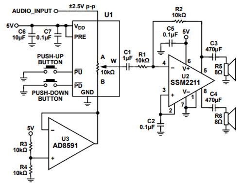
Digital potentiometers can be used in any type of application where ever the trimming potentiometer or present resistor is used as they can be controlled by a closed-loop. The most common application of a Digital potentiometer is for Audio Volume control. A typical application circuit diagram is given below, where the AD5259 IC is used with an Op-Amp amplifier IC to control the volume (gain) of the output audio.
The following are some of the applications where the digital potentiometers can be used
- To adjust the volume in stereo and other appliances
- To adjust the brightness and contrast in LEDs
- Programmable Voltage regulator
- Sensor auto referencing circuits
- To vary the resistance in an analog circuit
- Automatic Gain Control
- Used for sensor trimming and calibration instrumentation.
- Level adjustments in automotive electronics
- Programmable power supplies, filters, time constants or delay value.


