

Capable of supporting up to 32 GT/s without altering design
Understanding Film Capacitors and its Types with Applications

Capacitors are one of those imperative passive electrical components that are present in a wide range of circuits. If you are a DIY enthusiast who is passionate about electronic circuits, understanding the types of the capacitor is a must, to aptly use them in appropriate circuits. Here in this article, we help you decode and understand the uses of one of the most common types of capacitors called the film capacitors. We have already discussed the basics of capacitors, its types and where to use them. Do note that Film Capacitors are known by many names, some common ones are the Polyester Capacitors and Mylar Capacitor, this article covers all of them in general.
Generally, capacitors can be classified into two broad categories: Polarized and Nonpolarized. The film capacitor is a type of non-polarized capacitor and is quite popular due to its versatility and low cost. Read on to know more about a film capacitor: what is film capacitor, how it is made and what makes it so popular among its kind. Let’s start with a short introduction to this little passive device.
What is a film capacitor?
The film capacitor is a non-polarized capacitor and its dielectric is made using thin plastic films. These plastic films are sometimes metalized and are available in the market under the name “metalized capacitor”. These capacitors are sometimes also called as a metalized capacitor or plastic capacitors. A Thin Film Capacitor is nothing but bipolar capacitors with plastic films as their dielectric. These films are either metalized or just placed in layers to form out a roll or a candy-like the rectangular shape. The dielectrics popularly used are Polypropylene(PP)/ Polyethylene terephthalate (PET)/Polytetrafluoroethylene(PTFE)/ Polyphenylene Sulfide(PPS)
The main advantage of using a film capacitor is that it has a very low distortion factor and exceptional frequency characteristics. The wide range of plastic film used for different film capacitors, making them versatile. Also, these capacitors do not wear off quickly and are apt for high voltage and high-frequency applications such as coupling/decoupling circuits, ADC, audio circuits and many more. We have also previously discussed Bypass and decoupling capacitors which are the common applications for capacitors.
Understanding Film Capacitor, Polyester Capacitor, Mylar Capacitor, and Polypropylene Capacitor
Before we proceed with our article, we need to understand the meaning behind the popular terminologies Film Capacitor, Polyester Capacitor, Mylar Capacitor, and Polypropylene Capacitor. There are many types of Film Capacitors based on the type of plastic dielectric material used in the capacitor, out of which Polyester Capacitor and Polypropylene Capacitors are the most commonly used one.
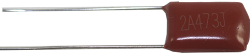
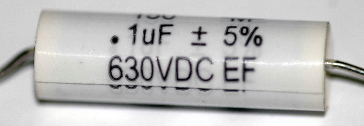
The Polyester Capacitor is also known as Polyester Film Capacitors has the dielectric material made of a polymer called polyethylene terephthalate (PET). This is the reason why this capacitor is sometimes referred to as PET Film Capacitor. There are many manufacturers for Polyester Capacitor and out of which Hostaphan is the leading one. Addressing the vendor name, the Polyester Capacitor is also sometimes called a Mylar Capacitor. A typical Mylar capacitor is shown below.
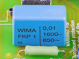
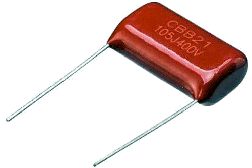
The Polypropylene Capacitor is another type of Film Capacitor in which the dielectric material is made of a polymer caller polypropylene (PP), hence the name Polypropylene Film Capacitor or PP Film Capacitor. A typical polypropylene capacitor is shown below
Similarly, there are more than 10 different types of Film capacitors based on the type of polymer used for the dielectric, the property of them changes slightly but the overall functionality and application almost remain the same. We will get into details later but before that let's dig into the history.
Brief History of Film Capacitors
Before film capacitors came in to picture, paper capacitors were used in the decoupling circuits. Paper capacitors used impregnated paper which was placed with metal strips and rolled into cylindrical shapes. However, since these capacitors had paper as a dielectric, they were not only likely to be prone to environmental defects and were quite bulky in size. Therefore, scientists began searching for a solution that would minimize these problems.
It was the time when the plastic industry was booming and scientists discovered how the use of particular plastic films as dielectric offered long term stability in terms of its electrical parameters. It also helped in reducing the size, as multilayers of papers were replaced by just a few sheets of plastic. As the technology advanced, the size of these capacitors was reduced as thinner plastics with high reliability.
Types of Film Capacitors and their Applications
Soon after the first film capacitor was introduced, the plastic industry saw its growth in developing thinner and more durable products. Different types of plastic film capacitors have been used over the years as a dielectric to suit different circuit applications. There are some film capacitors where the plastic films are just placed in between the aluminum foils and there are others where the plastic film is metalized through a process where the metal is deposited on the film itself. In general, film capacitors can be broadly classified into two types based on construction. Note that the classification is only based on construction.
Film/Foil Capacitors
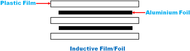
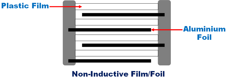
As the name suggests, the film/foil capacitor uses plastic films as dielectric and is placed inside two layers of electrodes made of aluminum foil. These interleaved layers are so structured that the metallic layers do not contact with each other. These capacitors can be either inductive or non-inductive.
An inductive film foil capacitor is wound in such a way that the aluminum foils are placed in the center of the two films. The aluminum foils are not connected to each other directly but through a leading wire that holds the whole winding. Figure 1 shows a pictorial representation of the same.
The aluminium foils in a noninductive fil foil capacitor are arranged such that each foil is placed out of the films to a certain extent, like that shown in figure 2.
Characteristics of Plastic Film Capacitor
- High insulation resistance
- Good capacitance stability
- High efficiency even at high frequency
- Dielectric used: Polypropelene(PP)/ Polyethylene terephthalate (PET)/Polytetrafluoroethylene(PTFE)
Application of Plastic Film Capacitor
Application of film/foil capacitor depends on the type of dielectric used.
- PET Film/foil capacitors are good for coupling, decoupling and bypassing.
- PP Film/Foil capacitors (PP) are a good option to be used in circuits that require high switching frequency like resonant and oscillator circuits, power supplies, etc.
Metalized film capacitors
The main difference between a film foil capacitor and a metalized capacitor is that in the latter instead of layering, the metallic electrodes are fused into either side of the plastic dielectric. Even though it increases the cost and also adds an extra step in the manufacturing process, it has superior stability and lesser dimensions than that in a film foil capacitor. The thickness of the plastic film can be as low as 0.6µm to get the desired capacitance value.
Characteristics of Metalized Film Capacitor:
- Self-healing property: This property enables the capacitor to repair itself rather than get short-circuited, in case the electrodes exposed to each other. This, in turn, increases the reliability of the capacitor
- Compact in size and shape
- Dielectric used:Polypropylene(PP)/ Polyethylene terephthalate (PET)/Polytetrafluoroethylene(PTFE)/ Polyphenylene Sulfide(PPS)
Application of Metalized Film Capacitor:
The metallic film capacitors are widely used in power electronic circuits including DC link circuits, pulse circuits, switching circuits, etc. The low power metalized film capacitor find their use in decoupling and filtering applications.
Features and Applications of Film Capacitors
Apart from the usual use of capacitors to accumulate the electric charges, the film capacitors offer other functions as well. The bipolar nature and exceptional frequency characteristics make them popular in high-frequency circuits. In general, the typical capacitance value for these capacitors lies in between 1nF to 30muF. These little passive components can be made to have a voltage rating as low as 50 V and as high as 2kV, therefore it can be used in a wide range of applications.
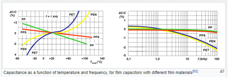
One of the interesting facts is that these film capacitors use different types of plastic film as a dielectric. Each type of film provides a different temperature and frequency characteristics to the capacitor in general. Hence, with the right choice of dielectric one can choose the optimal solution for their needs in their circuits. For example, if you are looking for a film capacitor to be placed in a circuit meant for high power/high-frequency applications, like say, induction heaters, the PP film capacitor would be the best choice.
The figure below shows the comparison between frequency and temperature characteristics of 4 different plastic film dielectrics namely PP, PPS, PEN, and PET. The only difference between these capacitors is the dielectric material and you can notice the change in temperature and frequency is quite apparent.
Film capacitors are known mainly for their low dissipation factor, stable capacitance, and high insulation resistance among others like negative temperature characteristics and high reliability. Therefore, they are popular choices for a wide range of applications. From simple sample/hold circuits for ADCs, oscillatory circuits, timers to finding a place in the coupling/decoupling units of high-end power electronic circuits, these film capacitors produce optimum performance.
These capacitors have replaced the use of ceramic and electrolyte capacitors in many circuits in automobile and industrial applications as well, over the past few decades. Let’s compare the film capacitor with the other popular capacitors and get to know what makes them a better choice for certain applications.
How is Film Capacitor different from Electrolytic Capacitor and Ceramic Capacitor?
The first difference which is quite evident between these three capacitors is the type of dielectric used and their construction. While the film capacitors use thin sheets of plastic films, ceramic capacitors have sheets made out of ceramic material as the dielectric. Both of them are bipolar in nature. The electrolytic capacitors, on the other hand, have oxides acting as dielectric and are polar in nature.
The differences in their manufacturing and dielectrics have a huge impact on their performances. As already discussed, the plastic film/metalized film capacitors are available in a wide range of capacitance values. The ceramic capacitors, on the other hand, are ideal only for circuits that have low capacitance requirements. For particular applications like analog signal processing and audio circuits, the film capacitors are preferred over ceramic capacitors due to the low distortion factor which they offer. Also at high capacitances, ceramic capacitors tend to have high nonlinearities which affect the performance of the circuits.
For applications such as coupling/decoupling circuits, capacitors with high capacitance and a low cost are preferred. Therefore, both electrolytic and Film capacitors are good options to choose from. Another major factor that is considered while designing such circuits is the ESR (Equivalent Series Resistance) and ESL (Equivalent Series Inductance) value of the capacitor. As already discussed, Film capacitors have better ESR and ESL value and very less distortion factor when compared to electrolytic capacitors and are therefore preferred over aluminium electrolytic capacitors.
Also, if we compare the aging time between these three capacitors, film capacitors tend to resist the wearing out stage for the longest time among them. This makes them a better choice for high voltage and high-frequency applications.
Construction of Film Capacitor
The generic manufacturing method for these capacitors starts by withdrawing a thin layer of plastic film. The thickness of this film decides the capacitance value. Since the capacitance value increases with a decrease in the distance between the electrodes, therefore a lower thickness of the film indicates a higher capacitance value. In general, the typical capacitance value for these capacitors lies in between 1nF to 30muF.
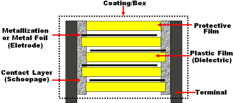
Once the film is extracted according to the desired capacitance value and the breakdown voltage, it is metalized with either aluminium or zinc and rolled over to form a “mother roll”. In the case of a film/foil capacitor, the films are just interleaved between sheets of aluminium foil to form the roll. The figure below shows a flow diagram of the various steps involved in the manufacturing of a metalized film capacitor.
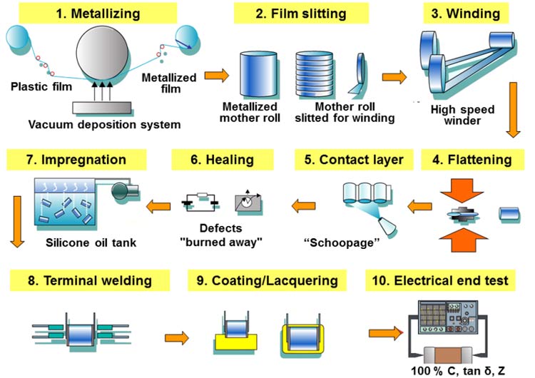
This roll is then manipulated through various processes like slitting, winding and flattening to suit the capacitor size and the desired electrical characteristics. Once the capacitor gets its desired shape and size, the projecting electrodes are subjected to a metalizing process called “Schoopage”. Here liquefied metals like zinc, aluminium or tin are used to create a protective layer on the electrodes. The lateral ends of the winding are then sprayed with compressed air and then subjected to a voltage, to burn away any existing defects on the surface of the electrodes.
Since the capacitors can get easily affected by moisture, the winding is impregnated with silicone oil or any other insulating fluid. Finally, this winding gets ready to be soldered to the metallic terminals of the capacitor. Once soldered, the capacitor is subjected to a final round of safety coating, where its body is dipped into a protected coating or potted on an external casing.


