

Capable of supporting up to 32 GT/s without altering design
Designing a Simple Over-Voltage Protection Circuit using Zener Diodes

Every circuit design operates at different voltage levels, the most common voltage levels for a digital circuit are 3.3V, 5V, and 12V. But every design is unique and it is also common for a circuit to have more than one operating voltage. A typical Computer SMPS system, for example, can operate on six different voltage levels namely, ±3.3V, ±5V, and ±12V. Different voltage levels will be used to power different types of components, in these cases, if a low power component is powered with a high voltage, the component will get permanently damaged. Hence the designer should always concentrate on implementing an Over Voltage protection circuit in his designs to prevent over-voltage damage.

Any component or circuit will have three different voltage ratings, namely minimum operating voltage, recommended or standard operating voltage, and maximum operating voltage. Any value above the maximum operating voltage can be fatal for any circuits or components. A very common and cost-effective solution is to use a Zener Diode Over Voltage Protection Circuit.
Zener Diodes - Basics
Zener diodes are mostly the first choice to protect the circuit from an overvoltage condition. A Zener diode follows the same principle of the diode, which is blocking the flow of current in the reverse direction. But there is a limitation that the Zener diode blocks current to flow in reverse direction only for a limited voltage specified by the Zener diode voltage rating. To be specific, a 5.1V Zener diode blocks current to flow in reverse direction up to 5.1V If the voltage across the Zener diode is more than 5.1V, it allows the current to pass through it. This feature of Zener diode makes it an excellent component for overvoltage protection.
How to protect circuits from overvoltage?
Consider the below image, where we need over-voltage protection for Microcontroller. The microcontroller can be anything that has a maximum rating of 5V across the IO pins. Therefore, more than 5V could damage the microcontroller.
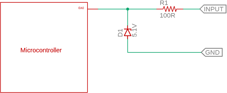
The Zener diode used in the above circuit is a 5.1V Zener diode. It will work fine during an over voltage situation. If the voltage is more than 5.1V, the Zener will pass the current and control the voltage up to 5.1V. But less than 5.1V, the Zener will act like a normal diode and block
Below image is a simulation of the Zener Diode Protection circuit on spice. You can check out the video at the bottom of this page for the complete simulation explanation.
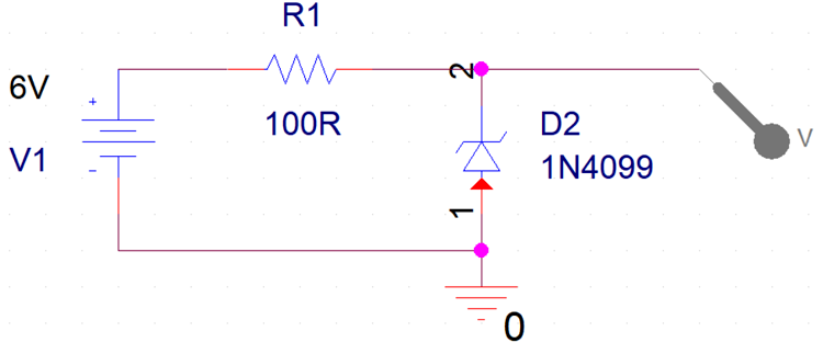
The above schematic has an input voltage, which is V1. The R1 and D2 are two components protecting the output from over-voltage protection. In this case, the D2, 1N4099 is a 6.8V Zener diode. The output will be protected if the V1 exceeds 6.8V. Due to the 6.8V reference voltage of the 1N4099, the output will remain 6.8V maximum.
Let's see how the above circuit acts as a Zener Diode Input Protection circuit and protects the output from voltage more than 6.8V.
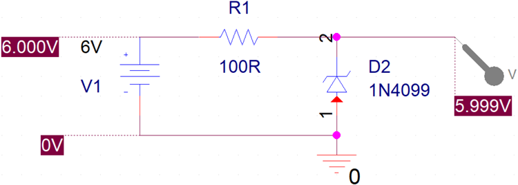
The above circuit is simulated using cadence pspice. During the 6V input voltage across the V1, the output remains constant at 5.999V (Which is 6.0V).
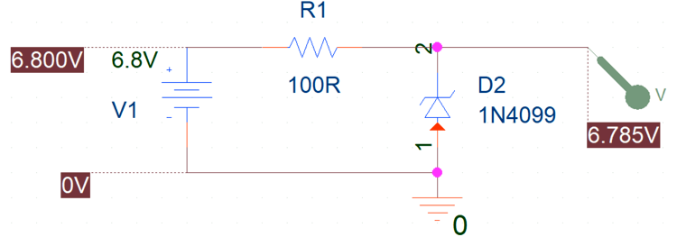
In the above simulation, the input voltage is 6.8V. Thus, the output is 6.785V which is close to the 6.8V. Let's increase the input voltage further and create an overvoltage situation.
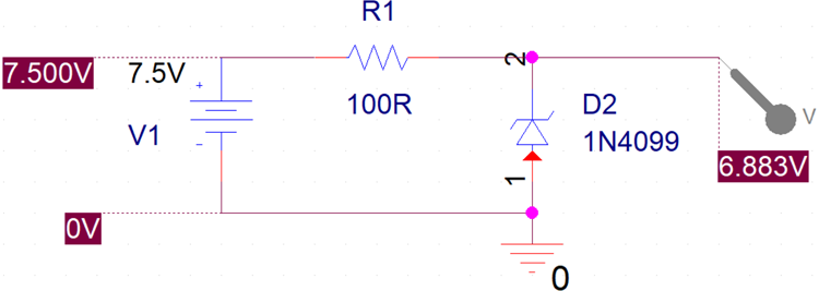
Now, the input voltage is 7.5V, which is more than the 6.8V. The output is still 6.883V now. This is how a Zener diode is effective to save the connected circuit from an overvoltage situation, also when the voltage goes back to less than 6.8V, he circuit will work normal again as shown in the previous step. Meaning, unlike a fuse, a Zener diode does not get damaged even during an overvoltage condition.
Any other Zener diodes with different values such as 3.3V, 5.1V, 9.1V, 10.2V can be used to select different overvoltage margins in the above circuit.
How to select a Zener diode for Overvoltage protection?
The next important part is to select the Zener diode value. The below points will help you in selecting the right value and part number for the Zener diode.
1. First, choose the Zener diode voltage. It is the voltage value where the Zener diode will act as a close circuit and protect the load from overvoltage. For the above example in Pspice, the Zener voltage is 6.8V.
There will be some situations where the targeted Zener diode voltage is not available. In such cases, a close value of the Zener diode can be chosen. For example, for overvoltage protection up to 7V, a 6.8V Zener diode is a close value.
2. Calculate the load current that is connected across the overvoltage protection circuit. For our example discussed above it is 50mA. Other than the load current, Zener diodes need biasing current. Therefore, the total current should be equal to the load current plus the Zener diode biasing current. For the example discussed above, it can be
Total current = 50mA + 10mA = 60mA
3. Zener diodes have a power rating. Thus, proper power rating Zener diode is required for proper heat dissipation. The power rating can be calculated based on the calculated total current in Step - 2 which is 60mA. Therefore, the Zener diode power rating will be equal to Zener diode voltage, ties the total current that will flow through the diode.
For our above example,
power rating = 6.8V x 0.060 = 0.408 Watt.
Therefore, a 500mW Zener diode will be sufficient.
4. Calculate the resistor value by differentiating the source voltage and the general voltage. The source voltage will be the maximum that can be applied to the circuit. For example, maximum overvoltage that can happen or can be applied as a supply voltage can be 13V.
Thus, the voltage drop across the resistor will be = 13V-6.8V = 6.2V As per the ohm's law, the resistor value will be = 6.2V / 0.060 A = 103R Standard value 100R resistor can be chosen.
Popular Zener diode values
|
Zener voltage |
Zener Diode part number |
|
3.3V |
1N5226 |
|
5.1V |
1N5231 |
|
6.8V |
1N5235 |
|
9.1V |
1N5239 |
|
11.0V |
1N5241 |
|
13.0V |
1N5243 |
|
15.0V |
1N5245 |
Zener Overvoltage Protection Circuit – Pros and Cons
OVP protection using Zener diodes is the easiest and simple process to protect devices from overvoltage. In this technique, the voltage remains regulated and the cost of this circuit is very less when compared with other methods.
But, certainly, this type of circuit has drawbacks. The major drawback of this type of circuit is the power dissipation. Due to the series resistor connected, it always dissipates heat and leads to wastage of the energy.


