

Capable of supporting up to 32 GT/s without altering design
Basics of Current Sense Amplifiers, its Types and Design Guide

Current Sense Amplifiers are special-purpose amplifiers that output a voltage that is proportional to the current flowing in the power rail. Current sense amplifiers are also called current shunt amplifiers because it uses a shunt resistor in the power rail that provides a small voltage drop when current flows through the resistor. This voltage drop is converted and amplified by the current sense amplifier into the small output voltage. You can also check out ACS712, which is also used for measuring current but uses a different hall effect based sensor.
These amplifiers are designed for the special purpose, so that the amplifier could amplify a very small amount of sensed voltage across the shunt resistor, typically in 10 to 100 mV range. Current Sense amplifiers are made for DC precision (For example, low input offset voltage) and high common-mode rejection ratio (CMRR). Current sense amplifiers can measure the current flowing in a single direction or it can measure current flow in both directions through the sense resistor. In such a case, if the amplifier is capable to detect current flow in both directions, it is called bidirectional current sense amplifiers.
In this article, we will evaluate different types of current sensing amplifiers using the example circuits.
Difference between Current Sense Amplifier and Normal Amplifier
Normal amplifiers and current sense amplifiers have different specifications and they are made for specific things. There are many types of Op-Amps, you can read this article to know the popular Op-Amps IC and their applications. Normal amplifiers could not amplify a very small amount of voltage and have low CMRR. On the other hand, precision current-sense amplifiers could detect and amplify a very small amount of voltages as well as the CMRR is relatively high.
For the normal differential amplifiers or standard operational amplifiers, the power source is connected between two power supply rails (Vcc and Vee) and the amplifiers can only operate on the signals that lie behind the power rails or have common ground paths. An outside voltage of the used power rail could trigger the internal ESD protection diodes if an external voltage is applied into the input pin of the standard amplifier and could cause a large current to flow.
But, current sense amplifiers are designed in a way that despite the low-voltage power rail (such as Vcc = 3.3 V and V = 0V), the amplifier can withstand a much higher pin voltage than the supplied Vcc. The amplifiers use an excellent power path protocol for its operation. Whenever the input voltage is lower than the VCC, the amplifier changes its input supply and gets powered from the input voltages.
Common Mode Voltage and CMRR
Common mode voltage is an important parameter for both normal amplifiers and current sense amplifiers. The common-mode voltage is the average voltage which is applied across the two inputs of the amplifier. This Voltage is so much important because the op-amp has limited capabilities to differentiate and produce output based on the common-mode voltage. A normal op-amp supports a small range of common-mode voltage that is not suitable for the precision level current sensing operations. But in the case of current sense amplifiers, the common-mode voltage ranges much wider than the actual supply voltage of the amplifier. For example, in the case of the current sense amplifier, INA240 is capable of supporting a common-mode voltage between -4 V to +80 V while running on supply as low as 2.7 V.
On the other hand, CMRR, the common-mode rejection ratio (CMRR) is the ratio of differential gain, and the common-mode gain. In the case of an ideal op-amp, the CMRR is infinite, but in practical circuits, it ranges typically 80 to 100 dB. The high CMRR denotes how much of the common-mode signal will reflect on the measurement. Thus, for a current sense amplifier, it is an important parameter as it will reflect the very low common-mode signal across the output, thus creating the possibilities to open up a wide range of current sensing capabilities. Current sense amplifiers have high CMRR and it could sense small common-mode signals. CMRR is also responsible for reducing noise on the current sense lines.
How to Design a Circuit using Current Sense Amplifier IC
Suppose a design with a 12V 1A line, where a high current sensing circuit needs to be used. In such a case, a current sense circuit can be built using current sense amplifiers. But before proceeding with the circuit, one needs to select a current sense amplifier for this purpose.
Since the maximum current rating is 1A, and no specified load is described, a current sense amplifier needs to be selected that works with 12V supply and could sense more than the 1A of the current rating. As discussed, one needs to select something for the low-level side or high-level side. In this case, a high side current sensing can be used for detecting a fault or proper short circuit condition. However, low side current sensing can also work. We will discuss the difference between these both later in this article.
Since the load could be capacitive or inductive, inrush current could occur, thus a low-value resistor can be used with a dedicated current sense amplifier. For this circuit, LT6108 can be used since it works with 2.7V to 60V. The CMRR of this amplifier is also very high, up to 125dB. Therefore, this amplifier could work in 12V supply as well as it could detect very low current flow.
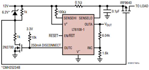
The above current sense amplifier circuit is build using LT6108. The 0.1 Ohms resistor is the sense resistor that could produce a voltage drop during the current flow through the resistor. On the other hand, the IRF9640 is the switching MOSFET that is controlled by the 2N2700 MOSFET. The amplifier could shut off the switching MOSFET for a pre-set value. In the above circuit, a trip point is created across 250mA. Thus the amplifier will shut off the load MOSFET if the current flow through the resistor crosses more than 250mA. However, for a trip voltage above 1A, the targeted value can be set by the voltage divider across the INC pin of the current sense amplifier. The Vout at OUTA pin of the current sense amplifier can be used to check the current flow rating through the current sense resistor.
The above circuit can also be constructed using another current sense amplifier that uses a wide range of supply voltage more than 12V and could accept the input irrespective of the supply voltage.
Types of Current Sensing ICs with Application Circuit
Low Side Current Sense
As discussed previously, a shunt resistor is used to sense the current, and depending on the shunt resistor placement, the current sense technique varies. A low side current measurement uses the. Due to this, the GND path of the active load is created in such a way that whenever the load current returns to the GND, it always flows through the shunt resistor. In the below images, low side current measurement circuits are shown.
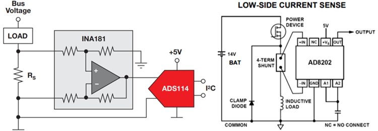
The above circuits are practical examples of the Low side current sensing technique. The left image is using the INA181Current Sense Amplifier from Texas Instruments and providing the output to an ADC that will provide the data in I2C protocol. The right image is using the AD8202 Current Sense Amplifier from Analog Devices. It is sensing Low side current of an inductive load.
Advantages:
The advantages of Low side current measurements are, it is simple to implement because the sense voltage across the current shunt resistor is in the GND referenced. In this configuration, a low voltage current sense amplifier can be used due to the small voltage drop across the shunt resistor. Also, due to the low sensed voltage, common-mode rejection can be ignored.
Disadvantages:
The major disadvantage of the low side current measurement is that the load gets offset from the ground-referenced. This happens due to the series placement of a shunt resistor in the ground plane. Due to the broken ground reference, this situation can become problematic in a short circuit situation between load and the ground as the shunt resistor unable to detect very high current flow through the load circuit.
High Side Current Sense
Same as Low side current sense, a high side current measurement uses the same current shunt resistor but the placement takes place between the power source and the active load. In the below images, high current sense amplifier circuits are shown.
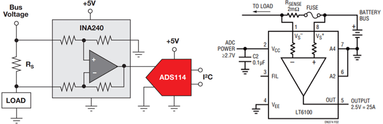
The above circuits are practical examples of the High side current sensing technique. The left image is using INA240 from Texas Instruments and providing the output to an ADC that will provide the data in I2C protocol. The right image is using LT6100 from Analog Devices. It is sensing High side current along with a fuse of a load.
Advantages:
High side current measurements have two advantages over low side measurements. First, It overrides the drawbacks of low side current sensing that is unable to detect load short circuit with the ground. Due to the placement of a shunt resistor in the power plain, it can easily detect the short circuit in load and ground.
Second, in this circuit, the load is placed in a proper ground referenced and the differential input from the shunt resistor could detect exact load current without additional effort if ADC conversion is used.
Disadvantages:
But the high side current measurement technique requires high common-mode rejection because the small voltage that is developed across the current shunt resistor is below the load supply voltage.
Bidirectional Current Sense
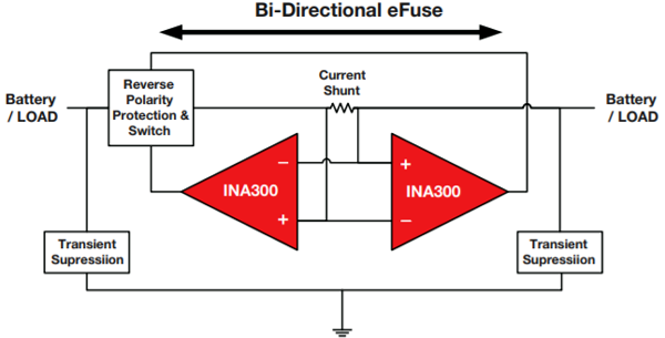
A bidirectional current sense circuit uses a simple shunt resistor but the amplifier needs capabilities to sense a wide range of common-mode voltages. The bidirectional current sense technique is a little bit complex than the Low and High side sensing. There are different ways to sense bidirectional currents. In some cases, such as the above image where two current sense amplifiers INA300 are connected in a way that will detect the current flow in both ways by anyone of the current sense amplifiers. The circuit requires Reverse polarity protection along with a switching technique that will switch the amplifier output depending on the polarity of the circuit.
Other ways to detect the bidirectional current is to use an input voltage for a reference, then the amplifier senses the drop voltage across the sense resistor and compares it with the reference voltage. If the drop voltage is above the known reference voltage, it is in one direction while the drop voltage below the known reference voltage is in the opposite direction.
Isolated Current Sense
Isolated current sensing technique uses proper CT transformer or hall effect induction that produces a proportional voltage in a transformer tap when current flows through another tap of the transformer.
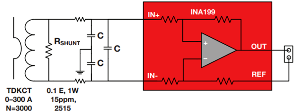
The above image is another practical example of the current sense amplifier using the isolated current transformer. It uses popular current sensing amplifier INA199 from Texas Instruments.
This is how current sensing amplifiers are used with different current sensing techniques.


